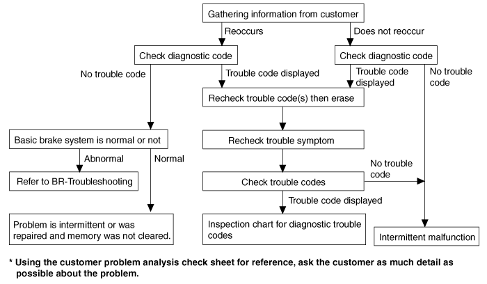
Standard Flow of Diagnostic Troubleshooting
Notes With Regard To Diagnosis
The phenomena listed in the following table are not abnormal.
Phenomenon
|
Explanation
|
System check sound
|
When starting the engine, a thudding sound can sometimes be heard
coming
from inside the engine compartment. This is because the system operation
check is being performed.
|
ABS operation sound
|
| 1. |
Sound of the motor inside the ABS hydraulic unit operation
(whine).
|
| 2. |
Sound is generated along with vibration of the brake pedal
(scraping).
|
| 3. |
When ABS operates, sound is generated from the vehicle
chassis due to
repeated brake application and release
(Thump : suspension; squeak: tires)
|
|
ABS operation (Long braking distance)
|
For road surfaces such as snow-covered and gravel roads, the braking
distance for vehicles with ABS can sometimes be longer than that for other
vehicles.
Accordingly, advise the customer to drive safely on such roads by
lowering the vehicle speed.
|
Diagnosis detection conditions can vary depending on the diagnosis
code. When checking the trouble symptom after
the diagnosis code has been erased, ensure that the requirements listed
in "Comment" are met.
|
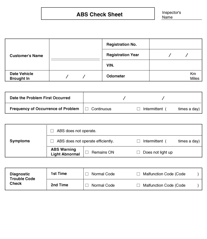
ABS Check Sheet
Problem Symptoms Table
If a normal code is displayed during the DTC check but the problem still
occurs, check the circuits for each problem symptom in the order given in the
table below and proceed to the relevant troubleshooting page.
Symptom
|
Suspect Area
|
ABS does not operate.
|
Only when 1.~ 4. are all normal and the problem is still occurring,
replace the HECU.
| 1. |
Check the DTC reconfirming that the normal code is output.
|
| 4. |
Check the hydraulic circuit for leakage.
|
|
ABS does not operate intermittently.
|
Only when 1.~4. are all normal and the problem is still occurring,
replace the ABS actuator assembly.
| 1. |
Check the DTC reconfirming that the normal code is output.
|
| 2. |
Wheel speed sensor circuit.
|
| 3. |
Stop lamp switch circuit.
|
| 4. |
Check the hydraulic circuit for leakage.
|
|
Communication with Scan tool is not possible.
(Communication with any system is not possible)
|
|
Communication with Scan tool is not possible.
(Communication with ABS only is not possible)
|
|
When ignition key is turned ON (engine OFF), the ABS warning lamp
does not light up.
|
| 1. |
ABS warning lamp circuit
|
|
Even after the engine is started, the ABS warning lamp remains ON.
|
| 1. |
ABS warning lamp circuit
|
|
|
During ABS operation, the brake pedal may vibrate or may not be
able to be depressed. Such phenomena are due to intermittent changes
in hydraulic pressure inside the brake line to prevent the wheels from
locking and is not an abnormality.
|

Detecting Condition
Trouble Symptoms
|
Possible Cause
|
Brake operation varies depending on driving conditions and road surface
conditions, so diagnosis can be difficult. However if a normal DTC is displayed,
check the following probable cause. When the problem is still occurring,
replace the ABS control module.
|
| -
|
Inoperative power source circuit
|
| -
|
Inoperative wheel speed sensor circuit
|
| -
|
Inoperative hydraulic circuit for leakage
|
|
Inspection Procedures
DTC Inspection
|
1. |
Connect the Scan Tool with the data link connector and turn the
ignition switch ON.
|
|
2. |
Is the ABS MIL on?
|

|
▶ Check the power source circuit.
|
|

|
▶ Read DTC and troubleshoot said DTC.
|
|
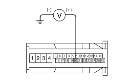
Check the Power Source Circuit
|
1. |
Disconnect the connector from the ABS control module.
|
|
2. |
Turn the ignition switch ON, measure the voltage between terminal
18 of the ABS control module harness side connector and body ground.
Specification:
approximately B+
|
|
|
3. |
Is the voltage within specification?
|
|
▶ Check the ground circuit.
|
|
|
▶ Check the harness or connector between the fuse (10A) in
the engine compartment junction block and the ABS control module.
Repair if necessary.
|

|
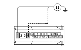
Check the Ground Circuit
|
1. |
Disconnect the connector from the ABS control module.
|
|
2. |
Check for continuity between terminals 1,4 of the ABS control
module harness side connector and ground point.
|
|
3. |
Is there continuity?
|
|
▶ No further action is required.
|
|
|
▶ Repair an open in the wire and ground point.
|
|
Check the Hydraulic Circuit
|
1. |
Refer to the DTC troubleshooting procedures.
|
|
2. |
Is the system operating to specifications?
|
|
▶ Check for DTC troublecodes.
|
|
|
▶ Check the hydraulic circuit for leakage.
|
|
Check the Hydraulic Circuit for Leakage
|
1. |
Refer to the hydraulic lines.
|
|
2. |
Inspect leakage of the hydraulic lines.
|
|
3. |
Is the system operating to specifications?
|
|
▶ The problem is still occurring, replace the ABS control
module.
|
|
|
▶ Replace the leaking hydraulic lines.
|
|

Detecting Condition
Trouble Symptoms
|
Possible Cause
|
Brake operation varies depending on driving conditions and road surface
conditions, so diagnosis can be difficult. However if a normal DTC is displayed,
check the following probable cause. When the problem is still occurring,
replace the ABS control module.
|
| -
|
Inoperative power source circuit
|
| -
|
Inoperative wheel speed sensor circuit
|
| -
|
Inoperative hydraulic circuit for leakage
|
|
Inspection Procedures
DTC Inspection
|
1. |
Connect the Scan Tool with the data link connector and turn the
ignition switch ON.
|
|
2. |
Is the ABS MIL on?
|
|
▶ Check the wheel speed sensor circuit.
|
|
|
▶ Read DTC and troubleshoot said DTC.
|
|
Check for DTC’s
|
1. |
Refer to the DTC troubleshooting procedures.
|
|
2. |
Is the system operating to specifications?
|
|
▶ Check the stop lamp switch circuit.
|
|
|
▶ Repair or replace the wheel speed sensor.
|
|
Check the Stop Lamp Switch Circuit
|
1. |
Check that stop lamp lights up when brake pedal is depressed and
turns off when brake pedal is released.
|
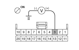
|
2. |
Measure the voltage between terminal 20 of the ABS control module
harness side connector and body ground when brake pedal is depressed.
Specification :
approximately B+
|
|
|
3. |
Is the voltage within specification?
|
|
▶ Check for DTC troublecodes.
|
|
|
▶ Repair the stop lamp switch. Repair an open in the wire
between the ABS control module and the stop lamp switch.
|
|
Check the Hydraulic Circuit for Leakage
|
1. |
Refer to the hydraulic lines.
|
|
2. |
Inspect leakage of the hydraulic lines.
|
|
3. |
Is the system operating to specifications?
|
|
▶ The problem is still occurring, replace the ABS control
module.
|
|
|
▶ Replace the leaking hydraulic lines.
|
|

Detecting Condition
Trouble Symptoms
|
Possible Cause
|
Possible malfunction in the power supply system (including ground)
for the diagnosis line.
|
| -
|
Inoperative power source circuit
|
|
Inspection Procedures
Check the Power Supply Circuit for the Diagnosis
|
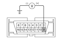
1. |
Measure the voltage between terminal 9 of the data link connector
and body ground.
Specification :
approximately B+
|
|
|
2. |
Is voltage within specification?
|
|
▶ Check the ground circuit for the diagnosis.
|
|
|
▶ Repair an open in the wire. Check and replace fuse (15A)
from the engine compartment junction block.
|
|
Check the Ground Circuit for the Diagnosis
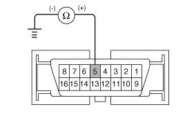
|
1. |
Check for continuity between terminal 5 of the data link connector
and body ground.
|
|
2. |
Is there continuity?
|
|
▶ Repair an open in the wire between terminal 5 of the data
link connector and ground point.
|

|

Detecting Condition
Trouble Symptoms
|
Possible Cause
|
When communication with Scan Tool is not possible, the cause may be
probably an open in the HECU power circuit or an open in the diagnosis output
circuit.
|
| -
|
Inoperative power source circuit
|
|
Inspection Procedures
Check for Continuity in the Diagnosis Line
|
1. |
Disconnect the connector from the ABS control module.
|
|
2. |
Check for continuity between terminals 11 of the ABS control module
connector and 1 of the data link connector.
|
|
3. |
Is there continuity?
|
|
▶ Check the power source of ABS control module.
|
|
|
▶ Repair an open in the wire.
|
|
Check the Power Source of ABS Control Module
|
1. |
Disconnect the connector from the ABS control module.
|
|
2. |
Turn the ignition switch ON, measure the voltage between terminal
18 of the ABS control module harness side connector and body ground.
Specification :
approximately B+
|
|
|
3. |
Is voltage within specification?
|
|
▶ Check for poor ground.
|
|
|
▶ Check the harness or connector between the fuse (10A) in
the engine compartment junction block and the ABS control module.Repair
if necessary.
|
|
Check for Poor Ground
|
1. |
Check for continuity between terminal 5 of the data link connector
and ground point.
|
|
▶ Replace the ABS control module and recheck.
|
|
|
▶ Repair an open in the wire or poor ground.
|
|

Detecting Condition
Trouble Symptoms
|
Possible Cause
|
When current flows in the HECU the ABS warning lamp turns from ON
to OFF as the initial check. Therefore if the lamp does not light up, the
cause may be an open in the lamp power supply circuit, a blown bulb, an
open in the both circuits between the ABS warning lamp and the HECU, and
the inoperative HECU.
|
| -
|
Inoperative ABS warning lamp bulb
|
| -
|
Blown No.2 fuse (10A) in the engine compartment junction
block
|
| -
|
Inoperative ABS warning lamp module
|
|
Inspection Procedures
Problem Verification
|
1. |
Disconnect the connector from the ABS control module and turn
the ignition switch ON.
|
|
2. |
Does the ABS warning lamp light up?
|
|
▶ It is normal. Recheck the ABS control module.
|
|
|
▶ Check the power source for the ABS warning lamp.
|
|
Check the Power Source for the ABS Warning Lamp
|
1. |
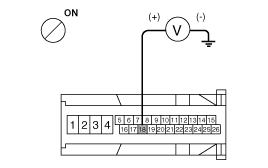
Disconnect the instrument cluster connector(M01-8) and turn the
ignition switch ON.
|
|
2. |
Measure the voltage between terminal 3 of the cluster harness
side connector(M01-8) and body ground.
Specification :
approximately B+
|
|
|
3. |
Is voltage within specification?
|
|
▶ Repair bulb or instrument cluster assembly.
|
|
|
▶ Check for blown fuse.
|
|
Check for Blown Fuse
|
1. |
Check continuity of fuse (10A) from the engine compartment junction
block.
|
|
2. |
Is there continuity?
|
|
▶ Repair an open in the wire between ABS fuse and 3 of cluster
connector(M01-8).
|
|
|
▶ Replace the blown fuse.
|
|

Detecting Condition
Trouble Symptoms
|
Possible Cause
|
If the HECU detects trouble, it lights the ABS warning lamp while
at the same time prohibiting ABS control. At this time, the HECU records
a DTC in memory. Even though the normal code is output, the ABS warning
lamp remains ON, then the cause may be probably an open or short in the
ABS warning lamp circuit.
|
| -
|
Inoperative instrument cluster assembly
|
| -
|
Inoperative ABS warning lamp module
|
|
Inspection Procedures
Check DTC Output
|
1. |
Connect the Scan Tool to the 16P data link connector located behind
the driver's side kick panel.
|
|
2. |
Check the DTC output using Scan Tool.
|
ABS Circuit Diagram(1)
ABS Circuit Diagram(2)
ECU Connector Input/Output(ABS)
Wire No.
Designation
Current
max.permissible wire resista ...
Components
1. Front - right tube
2. Rear - left tube
3. Rear - right tube
4. Front - left tube
5. Master cylinder tube2
6. Master culinder tube1
7. ABS co ...
 Hyundai Elantra: Troubleshooting

