 Hyundai Elantra: Schematic Diagrams
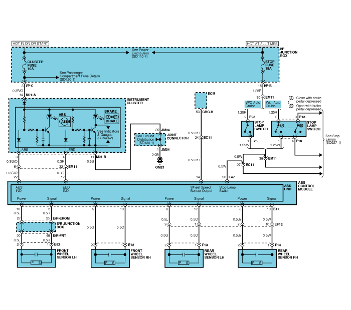
ABS Circuit Diagram(1)
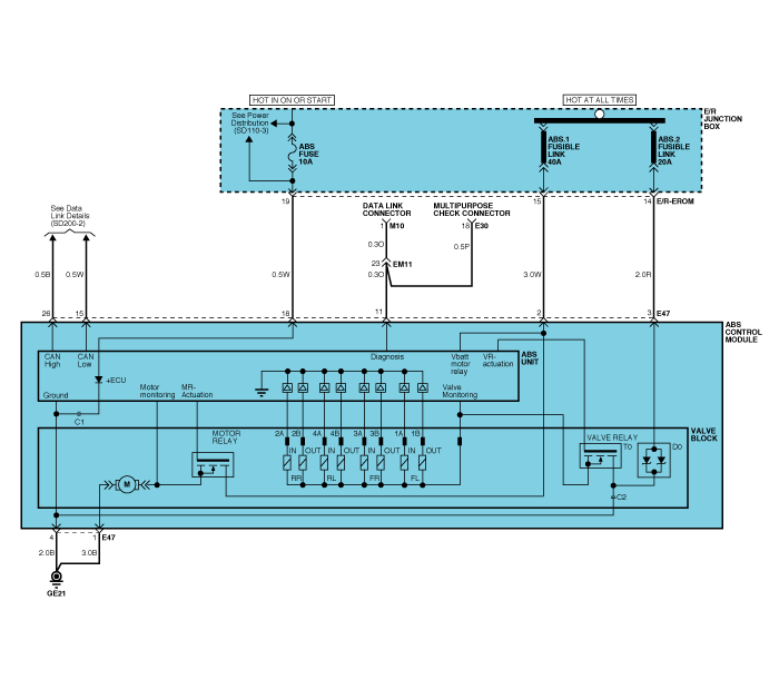
ABS Circuit Diagram(2)
ECU Connector Input/Output(ABS)

|
Wire No. |
Designation |
Current |
max.permissible wire resistance R_L (mΩ) |
min.leakage resistance R_P (kΩ) |
|
|
max |
min |
||||
|
1 |
Ground for recirculation pump |
20~39 A |
10 A |
10 |
|
|
4 |
Ground for solenoid valves and ECU |
5~15 A |
2.5 A |
10 |
|
|
2 |
Voltage supply for pump motor |
20~39 A |
10 A |
10 |
200 |
|
3 |
Voltage supply for solenoid valves |
5~15 A |
2 A |
10 |
200 |
|
18 |
Voltage for hybrid ECU |
1 A |
500 mA |
60 |
200 |
|
5,10,17,19 |
signal wheel speed sensor FL, FR, RL,RR |
16 mA |
6 mA |
250 |
200 to ground 1.5M to bat |
|
16,9,6,8 |
Voltage supply for the active wheel speed sensor FL,FR, RL, RR |
10 mA |
6 mA |
250 |
200 to ground 1.5M to bat |
|
11 |
Diagnostic wire K |
6 mA |
3 mA |
250 |
200 |
|
22 |
ABS-warning lamp actuation |
30 mA |
5 mA |
250 |
200 |
|
12 |
EBD-warning lamp actuation |
30 mA |
5 mA |
250 |
200 |
|
20 |
brake light switch |
10 mA |
5 mA |
250 |
200 |
|
15 |
CAN Low |
30 mA |
20 mA |
250 |
200 |
|
26 |
CAN High |
30 mA |
20 mA |
250 |
200 |
ABS HECU Connector
|
Connector terminal |
Specification |
Condition |
|
|
Number |
Description |
||
|
1 |
Ground for recirculation pump |
Current range: Min.10A Max.20~39A |
Always |
|
4 |
Ground for solenoid valves and ECU |
Current range: Min.2.5A Max.5~15A |
Always |
|
2 |
Voltage supply for pump motor |
Battery voltage |
Always |
|
3 |
Voltage supply for solenoid valves |
||
|
16 |
Voltage supply for the active wheel speed sensor FL,FR, RL, RR |
Battery voltage |
IG ON |
|
9 |
|||
|
6 |
|||
|
8 |
|||
|
5 |
signal wheel speed sensor FL, FR, RL,RR |
Voltage(High) : 0.89~1.26 V Voltage (Low) : 0.44~0.63 V |
On driving |
|
10 |
|||
|
17 |
|||
|
19 |
|||
|
11 |
Diagnostic wire K |
Voltage (High) ≥ 0.8 * IG ON Voltage (Low) ≤ 0.2 * IG ON |
On SCAN TOOL communication |
|
18 |
Voltage for hybrid ECU |
Battery voltage |
KEY ON/OFF |
|
20 |
Brake light switch |
Voltage (High) ≥ 4.5 * IG ON Voltage (Low) ≤ 2.0 * IG ON |
BRAKE ON/OFF |
Sensor Output On Scan Tool(ABS)
|
|
Description |
Abbreviation |
Unit |
Remarks |
|
1 |
Vehicle speed sensor |
VEH. SPD |
Km/h |
|
|
2 |
Battery voltage |
BATT. VOL |
V |
|
|
3 |
FL Wheel speed sensor |
FL WHEEL |
Km/h |
|
|
4 |
FR Wheel speed sensor |
FR WHEEL |
Km/h |
|
|
5 |
RL Wheel speed sensor |
RL WHEEL |
Km/h |
|
|
6 |
RR Wheel speed sensor |
RR WHEEL |
Km/h |
|
|
7 |
ABS Warning lamp |
ABS LAMP |
- |
|
|
8 |
EBD Warning lamp |
EBD LAMP |
- |
|
|
9 |
Brake Lamp |
B/LAMP |
- |
|
|
10 |
Pump relay state |
PUMP RLY |
- |
|
|
11 |
Valve relay state |
VALVE RLY |
- |
|
|
12 |
Motor |
MOTOR |
- |
|
|
13 |
Front Left valve(IN) |
FL INLET |
- |
|
|
14 |
Front Right valve (IN) |
FR INLET |
- |
|
|
15 |
Rear Left valve (IN) |
RL INLET |
- |
|
|
16 |
Rear Right valve (IN) |
RR INLET |
- |
|
|
17 |
Front Left valve (OUT) |
FL OUTLET |
- |
|
|
18 |
Front Right valve (OUT) |
FR OUTLET |
- |
|
|
19 |
Rear Left valve(OUT) |
RL OUTLET |
- |
|
|
20 |
Rear Right valve (OUT) |
RR OUTLET |
- |
|


