 Hyundai Elantra CN7: Cylinder Block
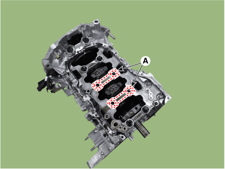
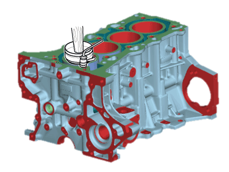
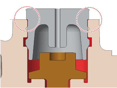
Water Jacket Insert
Components and components location
| Components |
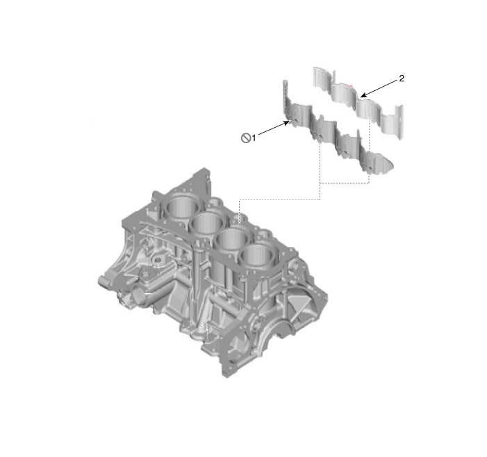
| 1. LH Water jacket insert | 2. RH Water jacket insert |
Repair procedures
| Removal and Installation |
| 1. | Remove the cylinder head. (Refer to Cylinder Head Assembly - "Cylinder Head") |
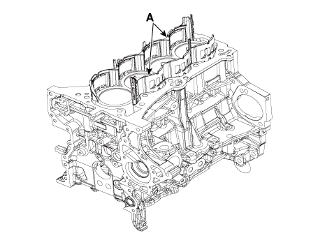
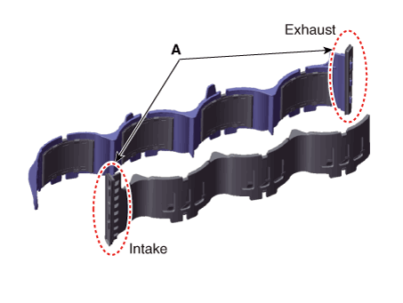
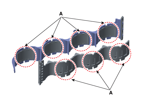
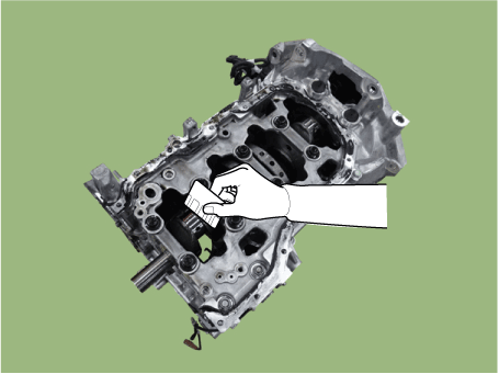
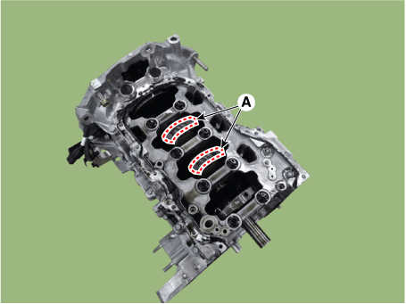
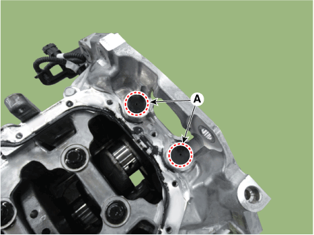
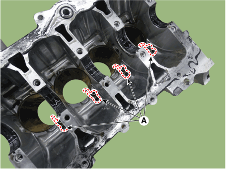
| 2. | Remove the RH water jacket insert and LH water jacket insert (A).
|

| 3. | Install in the reverse order of removal.
|
Fly Wheel
Repair procedures
| Removal and Installation |
| 1. | Remove the automatic transaxle. (Refer to Manual Transaxle System - "Manual Transaxle") (Refer to DCT (Dual Clutch Transmission) System - "Dual Clutch Transmission Assembly") |
| 2. | Remove the fly wheel (A).
|
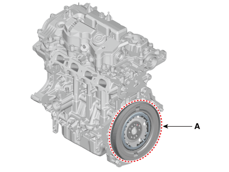
| 3. | Install in the reverse order of removal. |
Rear Oil Seal
Components and components location
| Components |
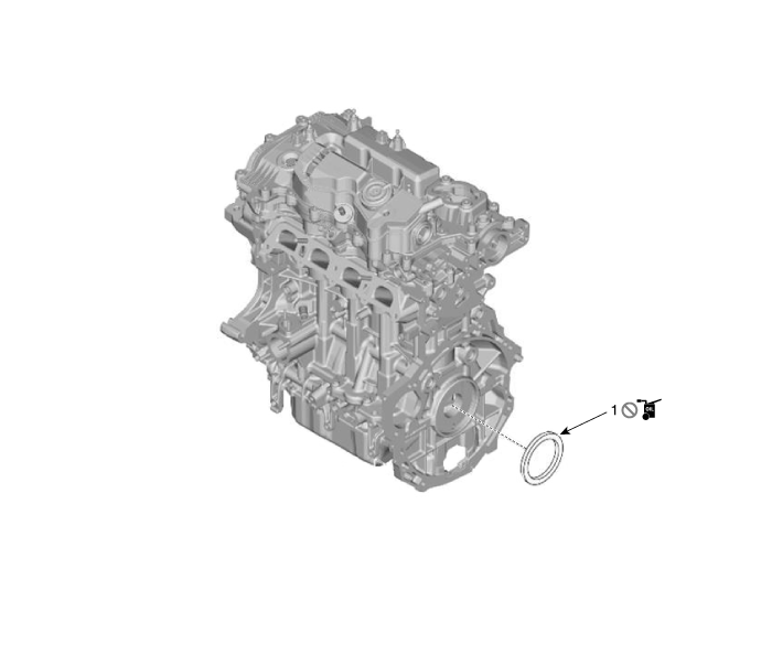
| 1. Rear oil seal |
Repair procedures
| Replacement |
| 1. | Remove the drive plate. (Refer to Cylinder Block - "Drive Plate") |
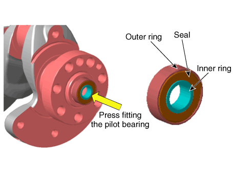
| 2. | Remove the rear oil seal (A).
|
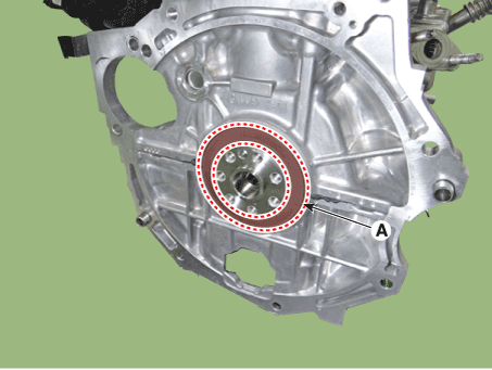
| 3. | Apply engine oil on the edge of new rear oil seal. |
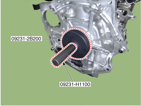
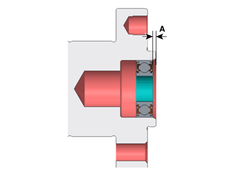
| 4. | Using SSTs (09231-H1100, 09231-2B200), install the new rear oil seal. When assembling, the surface of the oil seal shall coincide with the surface of the cylinder block.
|
| 5. | Install the other parts in the reverse order of removal. |
Piston and Connecting Rod
Repair procedures
| Disassembly |
|
|

| 1. | Remove the engine and transaxle assembly. (Refer to Engine and Transaxle Assembly - "Engine and Transaxle Assembly") |
| 2. | Remove the rear oil seal. (Refer to Cylinder Block - "Rear Oil Seal") |
| 3. | Install the engine assembly to engine stand for disassembly. |
| 4. | Remove the cylinder head. (Refer to Cylinder Head Assembly - "Cylinder Head")
|
| 5. | Remove the oil filter body. (Refer to Lubrication System - "Oil Filter & Oil Cooler") |
| 6. | Remove the oil pump. (Refer to Lubrication System - "Oil Pump") |
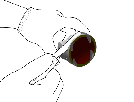
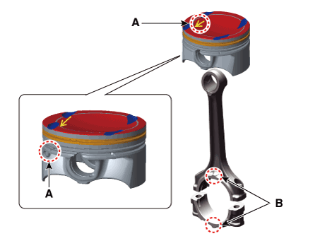
| 7. | Remove the piston and connecting rod assembly.
|
| 8. | Check fit between piston and piston pin. Try to move the piston back and forth on the piston pin. If any movement is felt, replace the piston and piston pin as a set. |
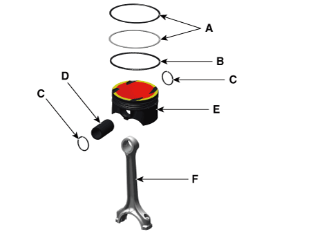
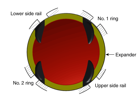
| 9. | Disassemble the piston rings.
|
| 10. | Disassemble the connecting rod from the piston.
|
| Inspection |
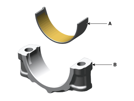
Connecting Rod
| 1. | Check the side clearance between piston and connecting rod. Using feeler gauge, measure the side clearance while moving the connecting rod back and forth.
|
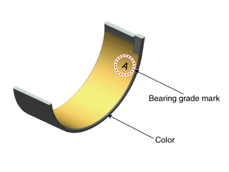
| 2. | Check the connecting rod bearing oil clearance.
| |||||||||||||||||||||||||||||||||||||||||||||||||||||||||||||||||||||||||||||||||||||||||||||||||||||||||||
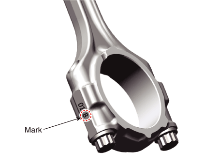
| 3. | Check the connecting rods.
|
Piston
| 1. | Clean the piston.
|
| 2. | Check the piston-to-cylinder clearance by calculating the difference between the cylinder bore inner diameter and the piston outer diameter.
|
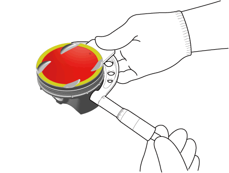
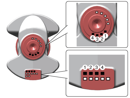
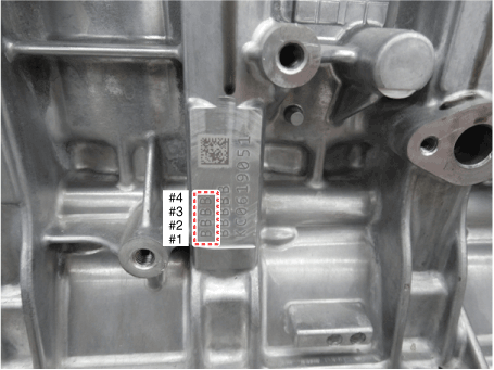
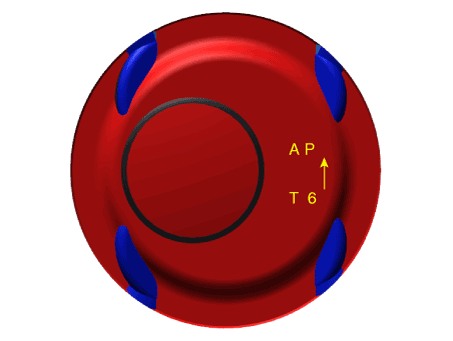
| 3. | Select the piston matching with cylinder bore class. (match classification mark)
|
Piston Rings
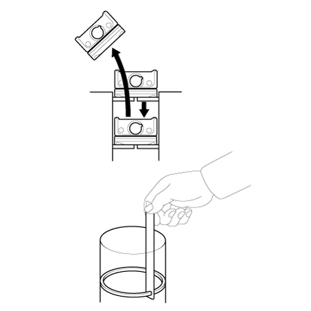
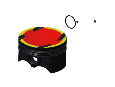
| 1. | Inspect the piston ring side clearance. Using a feeler gauge, measure the clearance between new piston ring and the wall of ring groove.
If the clearance is greater than maximum, replace the piston. |
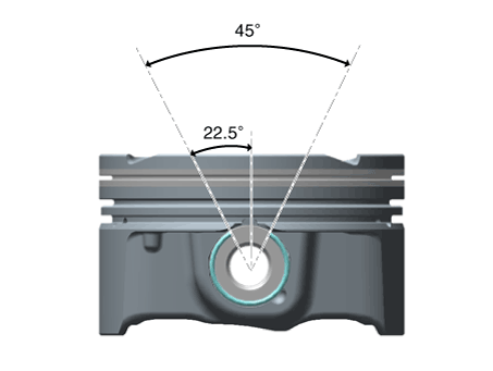
| 2. | Inspect the piston ring end gap. To measure the piston ring end gap, insert a piston ring into the cylinder bore. Position the ring at right angles to the cylinder wall by gently pressing it down with a piston. Measure the gap with a feeler gauge. If the gap exceeds the specifications, replace the piston rings. If the gap is too large, recheck the cylinder bore inner diameter.
|
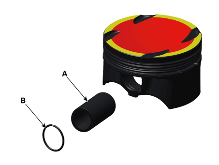
Piston Pin
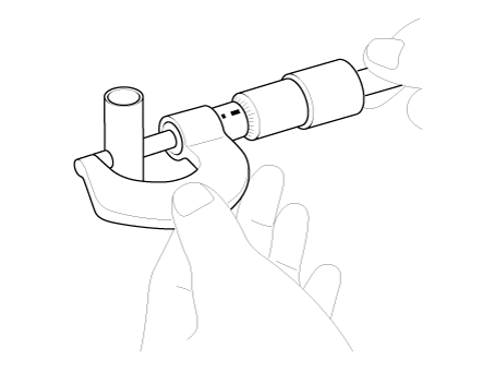
| 1. | Measure the outer diameter of piston pin
|
| 2. | Measure the piston pin-to-piston clearance.
|
| 3. | Check the difference between the piston pin outer diameter and the connecting rod small end inner diameter.
|
| Reassembly |
|
| 1. | Assemble the piston and the connecting rod.
|
| 2. | Install the piston rings.
|
| 3. | Install the connecting rod bearings.
|
| 4. | Install the piston and connecting rod assembly.
|
| 5. | Assemble the other parts in the reverse order of disassembly. |
Crankshaft
Repair procedures
| Disassembly |
|
|
| 1. | Remove the piston and connecting rod assembly. (Refer to Cylinder Block - "Piston and Connecting Rod") |
| 2. | Remove the air conditioning compressor. (Refer to Heating, Ventilation and Air Conditioning - "Compressor") |
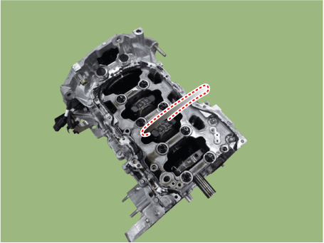
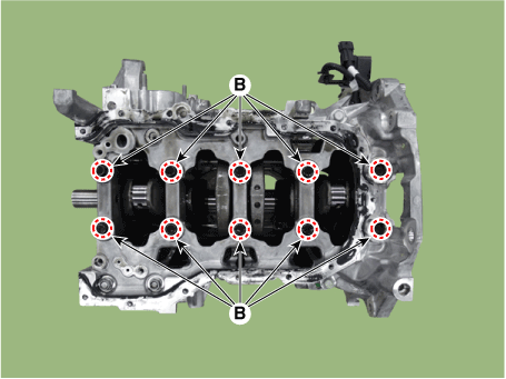
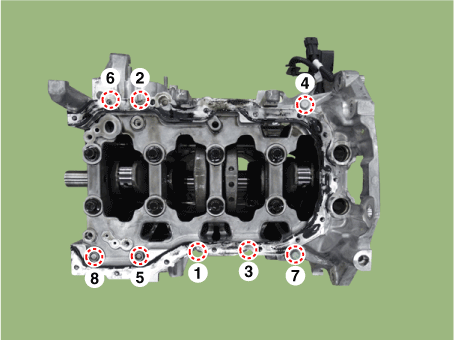
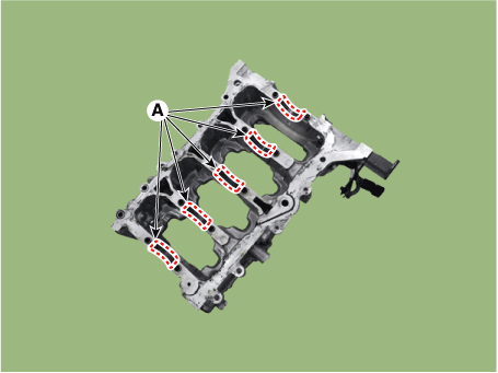
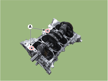
| 3. | Remove the rear caps (A).
|
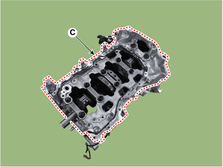
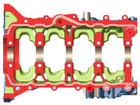
| 4. | Remove the lower crankcase.
|
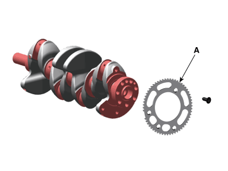
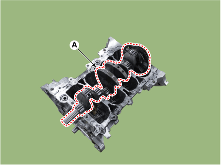
| 5. | Remove the crankshaft position sensor wheel (A).
|
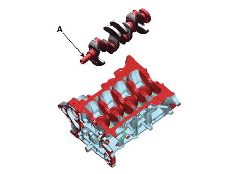
| 6. | Lift the crankshaft (A) out of the engine block, being careful not to damage journals.
|
| Inspection |
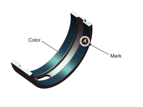
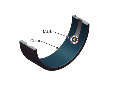
| 1. | Check the crankshaft bearing oil clearance.
| |||||||||||||||||||||||||||||||||||||||||||||||||||||||||||||||||||||||||||||||||||||||||||||||||||

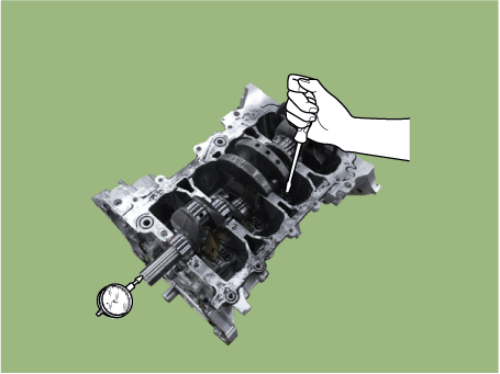
| 2. | Check the crankshaft end play. Using a dial indicator, measure the thrust clearance while prying the crankshaft back and forth with a screwdriver.
If the end play is greater than maximum, replace the thrust bearings as a set.
|
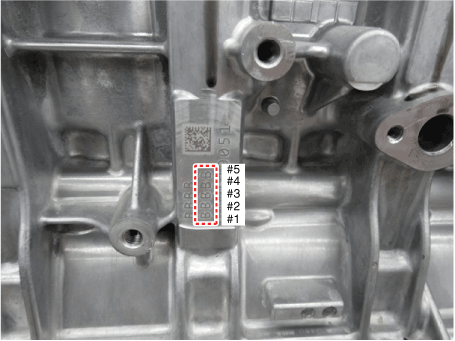
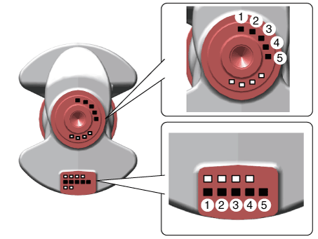
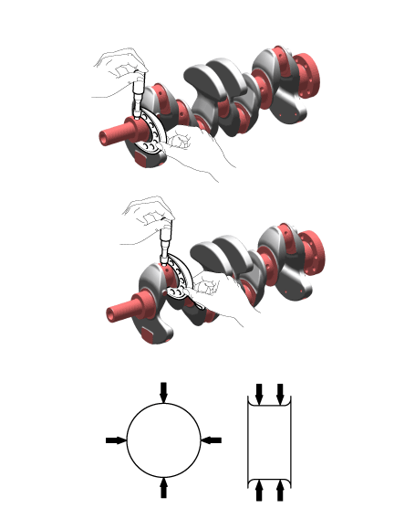
| 3. | Inspect the crankshaft main journals and pin journals. Using a micrometer, measure the diameter of each main journal and pin journal.
|
| Reassembly |
|
| 1. | Install the crankshaft position sensor wheel (A).
|
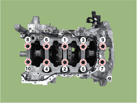
| 2. | Install the main bearing.
|
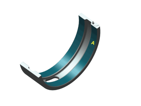
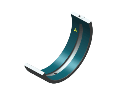
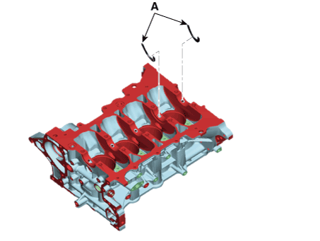
| 3. | Install the thrust bearings. Install the 2 thrust bearings (A) on both sides of the No.4 journal of the cylinder block with the oil groove facing out.
|
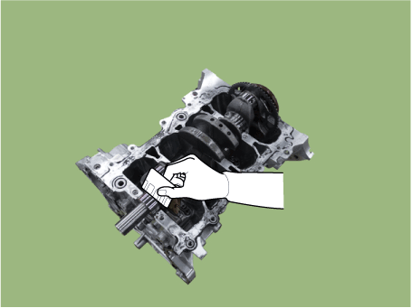
| 4. | Place the crankshaft (A) on the cylinder block.
|
| 5. | Install the lower crankcase.
|
| 6. | Check the crankshaft end play. |
| 7. | Install the piston and connecting rod assemblies. (Refer to Cylinder Block - "Piston and Connecting Rod") |
| 8. | Assemble the other parts in the reverse order of disassembly.
|
Cylinder Block
Repair procedures
| Disassembly |
|
|
| 1. | Remove the crankshaft. (Refer to Cylinder Block - "Crankshaft") |
| 2. | Remove the water jacket insert. (Refer to Cylinder Block - "Water Jacket Insert") |
| 3. | Remove the knock sensor. (Refer to Engine Control / Fuel System - "Knock Sensor (KS)") |
| 4. | Remove the crankshaft position sensor (CKPS). (Refer to Engine Control / Fuel System - "Crankshaft Position Sensor (CKPS)") |
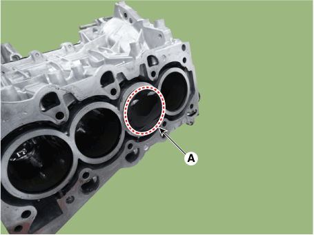
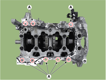
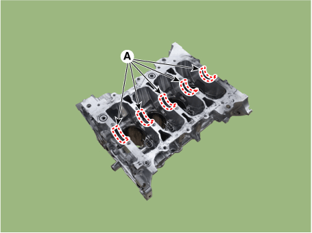
| 5. | Remove the piston cooling oil jets (A).
|
| Inspection |
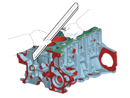
| 1. | Using a gasket scraper, remove all the gasket material from the top surface of the cylinder block. |
| 2. | Using a soft brush and solvent, thoroughly clean the cylinder block. |
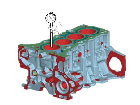
| 3. | Inspect the top surface of cylinder block for flatness. Using a precision straight edge and feeler gauge, measure the surface contacting the cylinder head gasket for warpage.
|
| 4. | Visually check for scratches on the inside surface of the cylinder bore and replace the cylinder block if any noticeable scratch is detected. If deep scratchs are present, replace the cylinder block. |
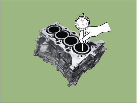
| 5. | Using the cylinder bore gauge, measure the cylinder bore’s inner diameter to the axial and axial perpendicular directions.
|
| Reassembly |
|
| 1. | Install the piston cooling oil jets (A).
|
| 2. | Install the crankshaft. (Refer to Cylinder Block - "Crankshaft") |
| 3. | Check the crankshaft end play. (Refer to Cylinder Block - "Crankshaft") |
| 4. | Disconnect the lower crankcase and check crankshaft bearing oil clearance. (Refer to Cylinder Block - "Crankshaft") |
| 5. | Install the piston and connecting rod assembly. (Refer to Cylinder Block - "Piston and Connecting Rod") |
| 6. | Check the connecting rod bearing cap oil clearance. (Refer to Cylinder Block - "Piston and Connecting Rod") |
| 7. | Check the connecting rod end play. (Refer to Cylinder Block - "Piston and Connecting Rod") |
| 8. | Assemble the other parts in the reverse order of disassembly.
|


