 Hyundai Elantra: TPMS Sensor. Repair procedures
Removal
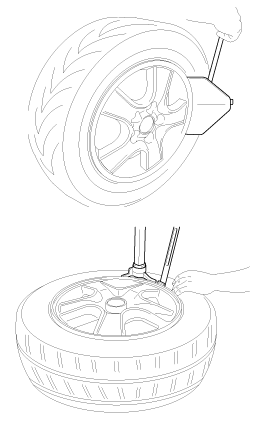
Tire Removal
| 1. |
Deflate tire & remove balance weights.
|
Sensor Removal
Handle the sensor with care.
|
| 1. |
Remove the valve nut.
|
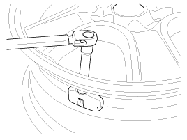
| 2. |
Discard the valve assembly.
|
Installation
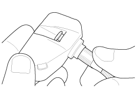
Sensor Fit
|
| 1. |
Assemble valve to sensor and turn valve 3 times with
the square part of the screw in the slot.
|
| 2. |
Mount assembly to wheel.
|
| 3. |
Tighten washer and nut by hand until the valve thread
meets the nut built-in calibrated stop.
|
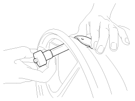
| 4. |
Using a torque wrench, tighten the nut to 2.95±0.37
lb-ft (4.0±0.5 Nm) It is normal to feel a break as the 1.7 lb-ft (2.3Nm)
calibrated stop in the nut snaps and the torque falls.
|
Tire Fit
Only use wheels designed to accommodate the TPMS
sensor.
|
| 1. |
Lubricate the tire bead not the rim. Excessive lubrication
should not be applied.
|
| 2. |
Start tire mounting approx. 5.9 in(15 cm) from valve.
|
| 3. |
Move the mounting tool away from the valve.
|
| 4. |
Finish with mounting tool near to valve.
|
| 5. |
Perform inflation / pressure correction and then
fit valve cap.
|
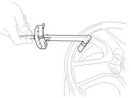
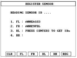
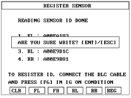
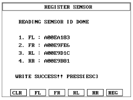
Sensor Initiating Procedure
| 1. |
Read the four sensor's ids starting with sensor 1
(1 normally front left, 2 front right, 3 rear left, 4 rear right).
|
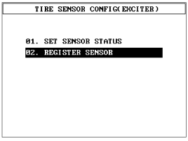
| 2. |
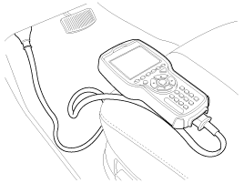
Connect 'TPMS exciter' to the diagnostic connector.
|
| 3. |
Register the four sensor's ids to the receiver.
|
| 4. |
Disconnect diagnostic link.
|
| 5. |
Cycle Ignition, wait 4 minutes and check that Normal
Receiver State is now indicated.
|


