 Hyundai Elantra CN7: Tire Pressure Monitoring System
Description and operation
| Description |
The Tire Pressure Monitoring System (TPMS) monitors the pressure and temperature inside the tire in order to warn the driver of changes in pressure which may influence the operation of the vehicle. The TPMS control module analyzes wireless information fro
In other words, the system detects the pneumatic pressure of the tires and warns the driver of if the pneumatic pressure drops below the standard level.
Tire low-pressure warning light

Lamp ON/OFF Conditions when the Tire Pressure Decreases or Air is Leaking from the Tire
| 1. | Lamp ON
|
| 2. | Lamp OFF
|
TPMS Fault Warning Lamp
| 1. | Warning Conditions and Display
|
| 2. | Lamp OFF
|


System Defect
| 1. | General Operation
The following are major defects:
|
Components and components location
| Components |
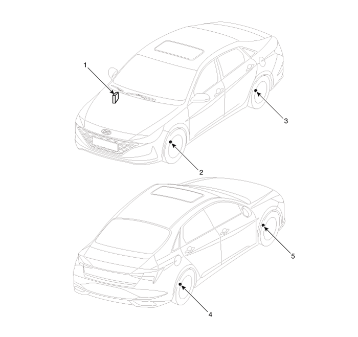
| 1. Integrated Body Control Unit (IBU) 2. TPMS sensor (FL) 3. TPMS sensor (RL) | 4. TPMS sensor (RR) 5. TPMS sensor (FR) |
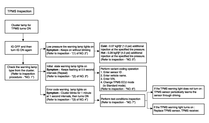
Troubleshooting
| TPMS Inspection method |
TPMS Sensor
Description and operation
| Description |
| 1. | Function
|
| 2. | Structure and features
|
| 3. | Mode
|
Automatic Location Learning Perform
| • | After stopping or parking for more than 19 minutes, automatic learning function in every driving position is performed. |
| • | The sensor is converted to Parking Mode when stopped or parked for more than 15 minutes. When acceleration of over 4g (15-20km/h) is detected in Parking Mode, it is converted to First Block Mode. |
Repair procedures
| Removal |
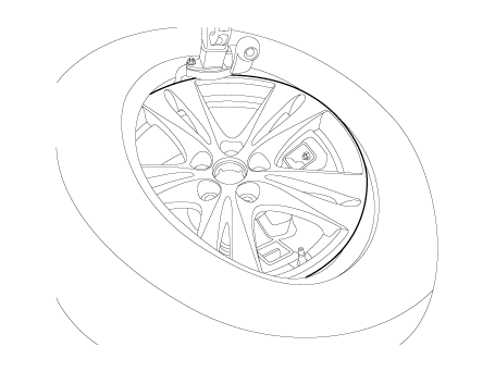
| 1. | Remove the wheel and tire. (Refer to Suspension System - "Wheel") |
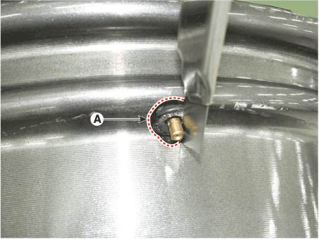
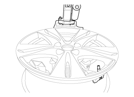
| 2. | Remove the screw with torx driver (A).
|
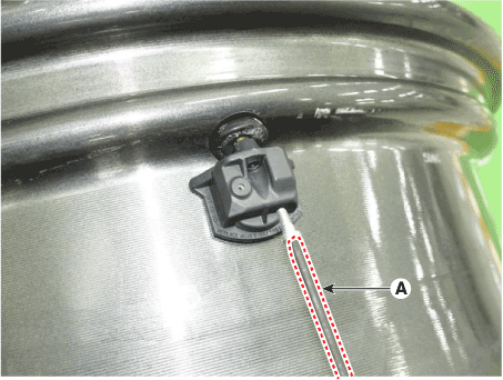
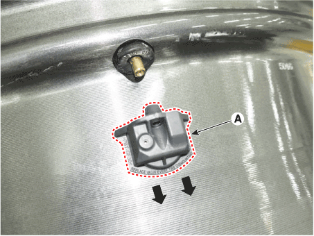
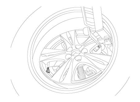
| 3. | Remove the sensor body (A) in the direction of the arrow.
|
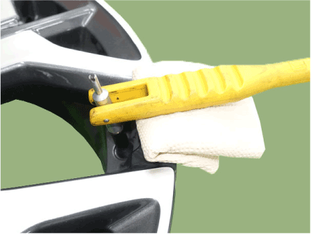
| 4. | Use the valve mounting tool to pull out the valve until it is entirely out of the lower hole.
|
| 5. | Apply lubricant to the surface of the new valve, and then mount it through the valve hole of the wheel.
|

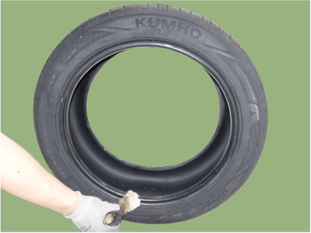
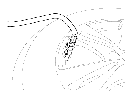
| 6. | Apply soapy water or lubricant to the upper/lower bead section of the tire.
|
| 7. | To fit the bottom bead, position the sensor at the 5 o’clock position relative to the head on the tire changing machine
|
| 8. | Rotate the rim clockwise, and push down on the tire at the 3 o’clock position to fit bottom bead.
|
| 9. | Push down on the tire at the 3 o’clock position and rotate the rim clockwise to fit the top bead.
|
| 10. | Inflate the tire until beads seat.
|
| 11. | Adjust the tire pressure according to the recommended tire pressure for the vehicle.
|
| 12. | If the TPMS sensor malfunctions, you must perform TPMS sensor learning. Replace any faulty sensors and perform TPMS sensor learning. |
| Diagnostic Procedure Using a Diagnostic Instrument |
The following section describes how to diagnose faults using a diagnostic instrument.
| 1. | Connect the diagnostic instrument to the self-diagnostic connector (16-pin) beneath the crash pad on the side of driver's seat, and then turn on the ignition to activate the diagnostic instrument. |
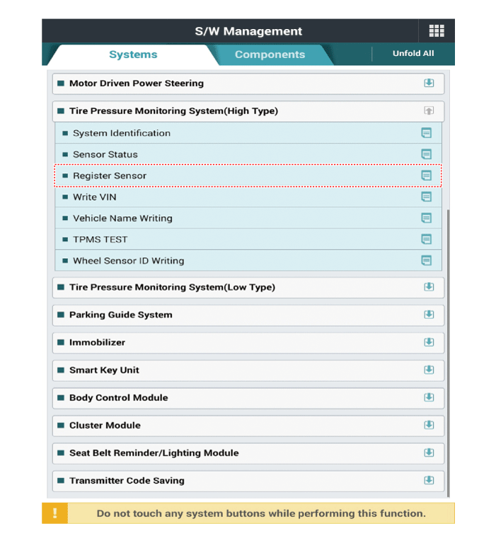
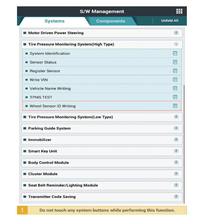
| 2. | In the GDS Vehicle Type Selection menu, select "Vehicle Type" and "TPMS" System, and then opt for "OK." |
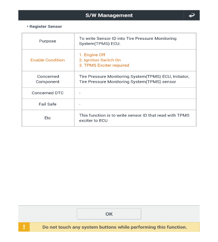
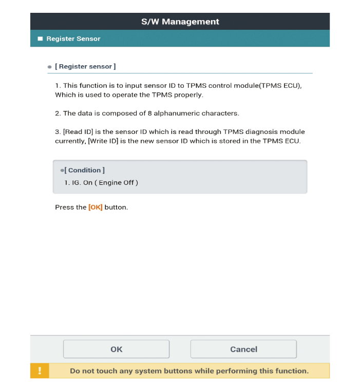
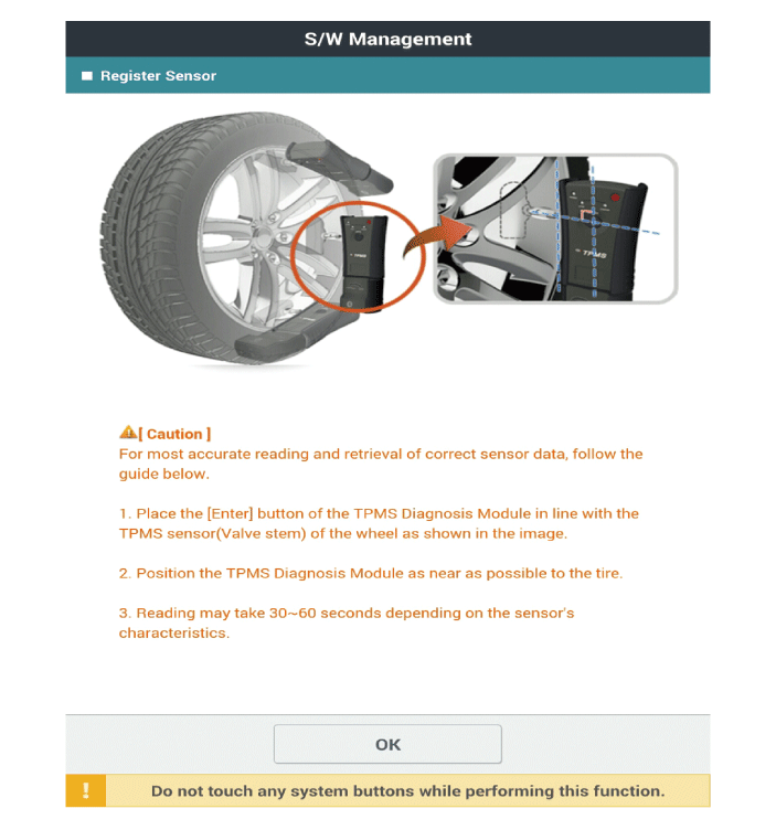
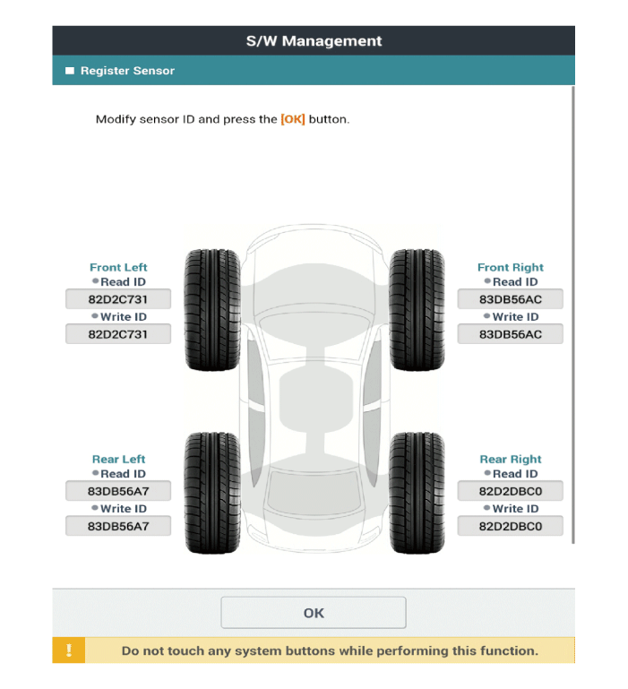
[Register Sensor Method]
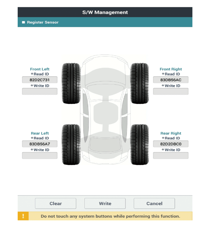
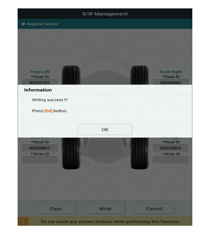
|
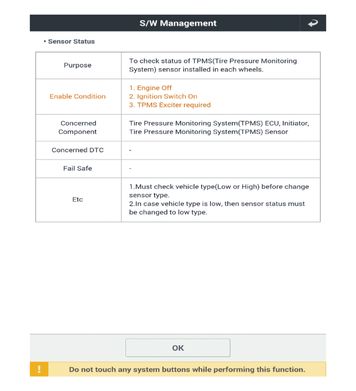
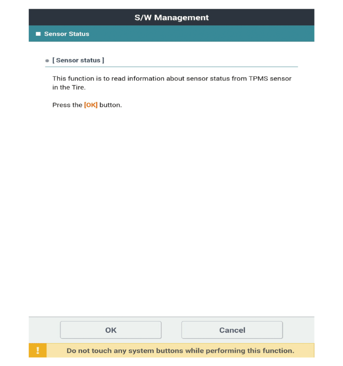
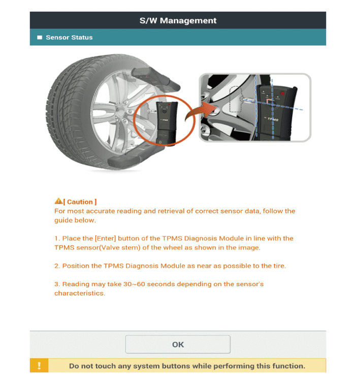
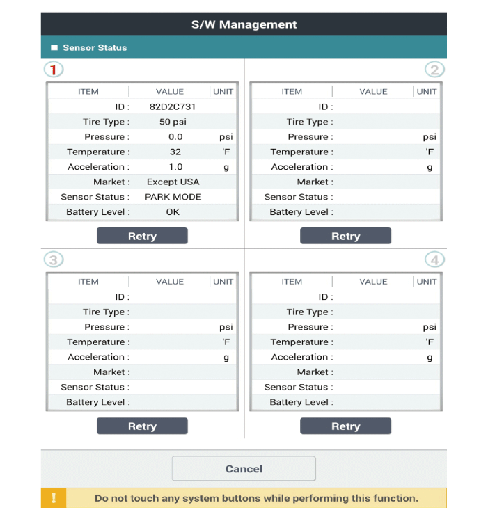
[Sensor Status Method]

|
TPMS Receiver
Description and operation
| Description |
TPMS Receiver : BCM(body control module) integrated management
| 1. | Early state
|
| 2. | Normal State
|
| Operation |
| 1. | General Function
|
| 2. | General Conditions to Learn New Sensors
|
| 3. | General Conditions to Un-Learn a sensor that is removed
|
Repair procedures
| Replacement |
[TPMS Receiver (Integrated Body Unit (IBU))]
| 1. | Turn the ignition switch OFF and disconnect the battery negative (-) cable. |
| 2. | Remove the glove box. (Refer to Body - "Glove Box") |
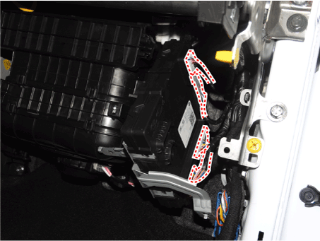
| 3. | Remove the IBU (A) after loosening the mounting nuts and bolt.
|
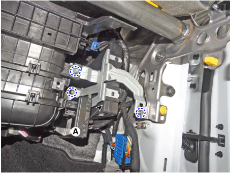
| 4. | Remove the IBU after disconnecting the connector.
|
| 5. | To install, reverse the removal procedures. |
| 6. | learn by connecting diagnostic tool. |
| 7. | Perform TPMS test to check for any abnormality. |
| Diagnosis procedure by using diagnostic device |
The main contents of diagnostic method using diagnostic device are as follows:
| 1. | Connect self-diagnosis connector (16 pins) located in the lower driver side crash pad to self-diagnosis device, and then turn on the self-diagnosis device after key is ON. |
| 2. | Select the "vehicle model" and "TPMS" on GDS vehicle selection screen, then select OK. |
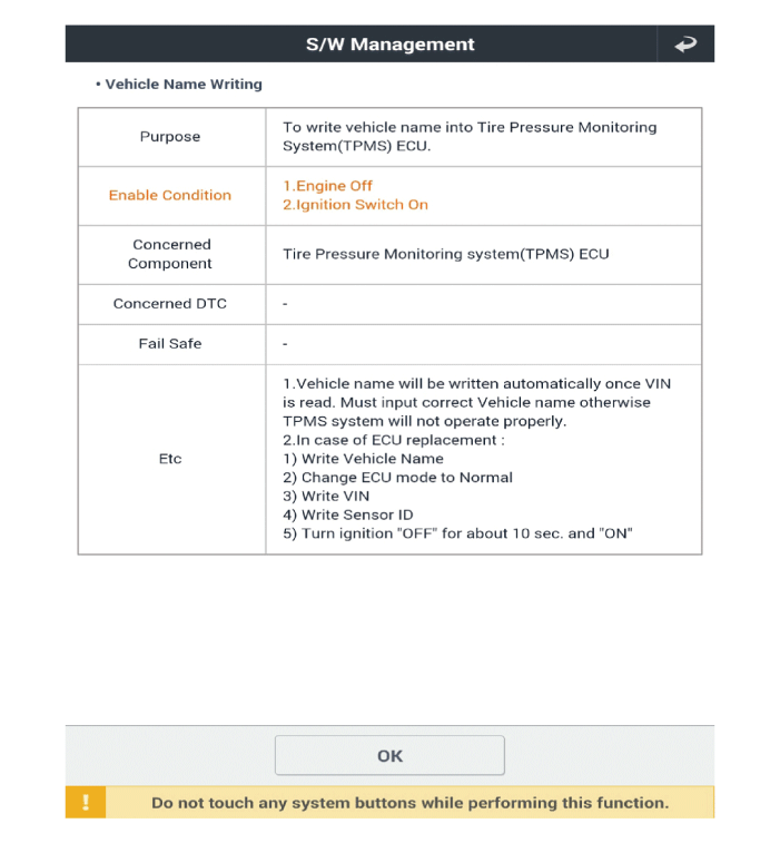
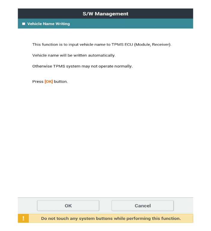
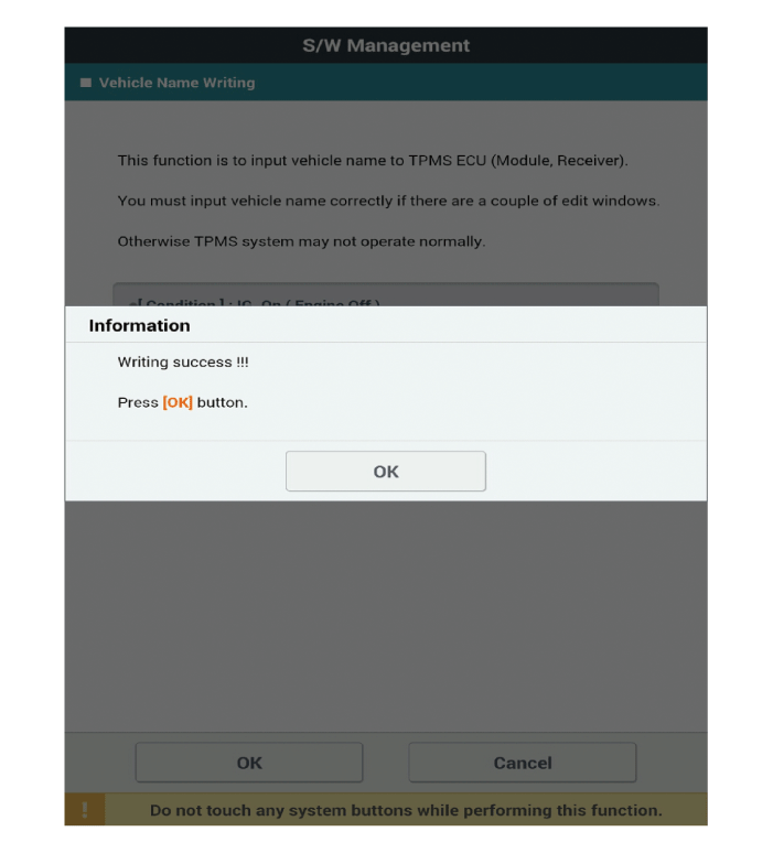
[Vehicle Name Writing Method]


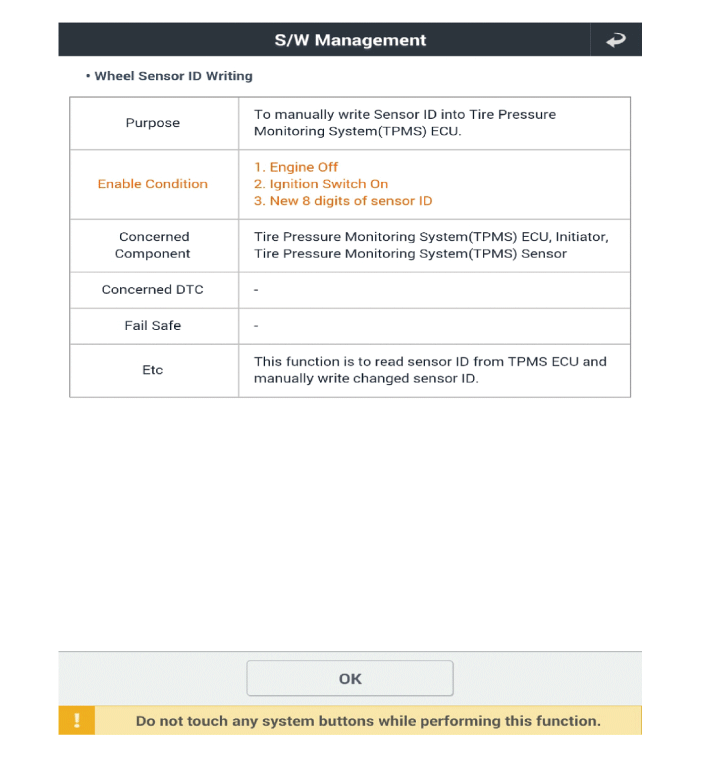
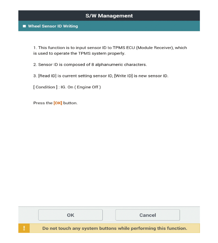
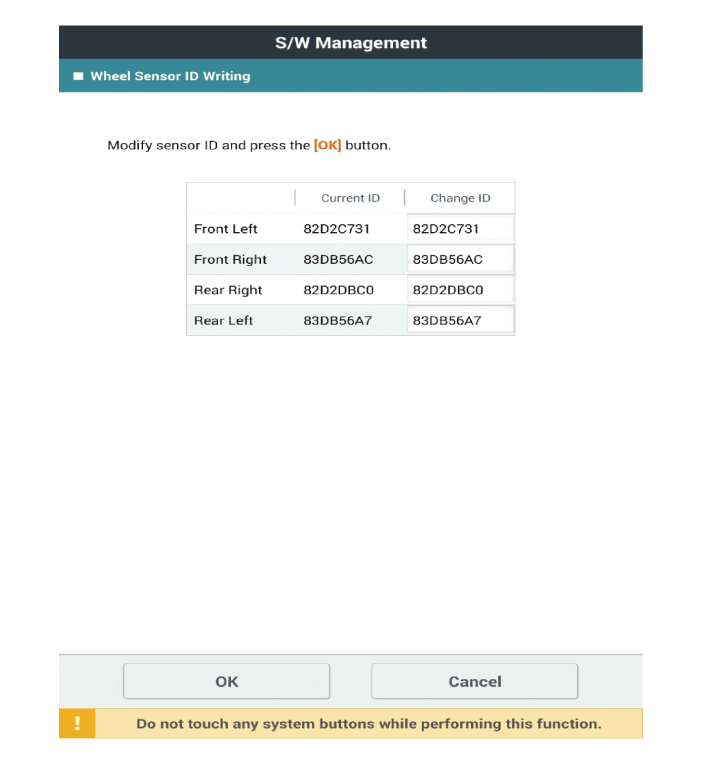
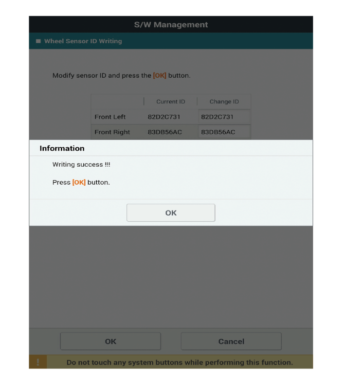
[Wheel Sensor ID Writing Method]
| Inspection |
| 1. | Check the vehicle code, VIN, sensor ID storage and normal storage in the receiver. |
| 2. | Check if the TPMS receiver [Integrated Body Unit (IBU)] status is normal. |
| 3. | Check whether the TPMS warning light is off and DTC. |


