 Hyundai Elantra: Steering Gear box. Repair procedures
Removal
| 1. |
Remove the front wheel & tire.
|
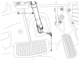
| 2. |
Loosen the bolt (A) and then disconnect the universal joint assembly
(B) with the pinion of the steering gear box.
|
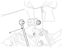
| 3. |
Disconnect the stabilizer link (A) from the front strut assembly
by loosening the nut.
|
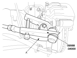
| 4. |
Remove the split pin and castle nut and then disconnect the tie
rod end (A) with the knuckle by using a SST (09568-34000).
|
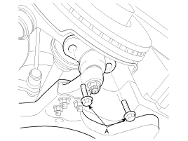
| 5. |
Disconnect the front lower arm with the knuckle by loosening the
mounting bolts (A).
|
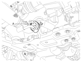
| 6. |
Remove the muffler rubber hanger (A).
|
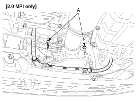
| 7. |
Loosen the wiring harness protector bolts (A).
|
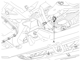
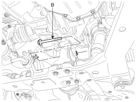
| 8. |
Remove the front and rear roll stopper bolt and nut (A, B).
|
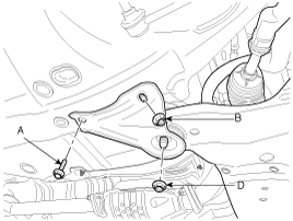
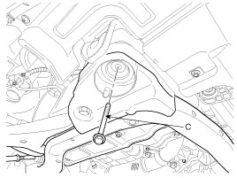
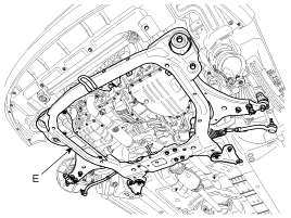
| 9. |
Remove the sub frame (E) and sub frame stay by loosening the mounting
bolts (A, C) and nuts (B, D).
|
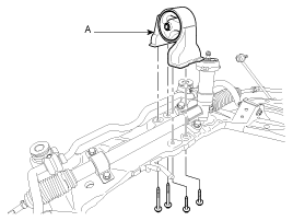
| 10. |
Remove the rear roll stopper (A) from the sub frame by loosening
mounting bolts.
|
| 11. |
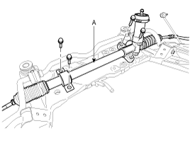
Remove the steering gear box (A) from the sub frame by loosening
the mounting bolts.
|
Disassembly
| 1. |
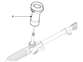
Remove the dust packing & cap (A) from the pinion housing.
|
| 2. |
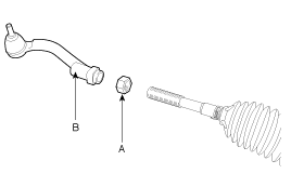
Loosen the lock nut and then remove the tie rod end (B) and lock
nut (A) from the tie rod.
|
| 3. |
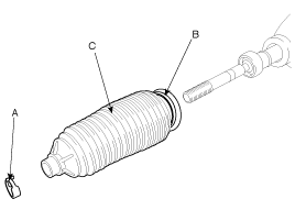
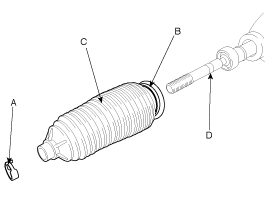
Remove the bellows clip (A) and band (B) and then pull the bellows
(C) away from the end of the tie rod.
|
| 4. |
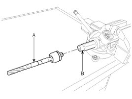
Remove the tie rod (B) from the rack bar (A) by unscrewing the
tie rod inner ball joint.
|
| 5. |
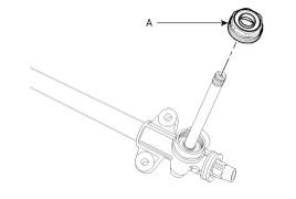
Remove the plug (A) from the pinion housing.
|
| 6. |
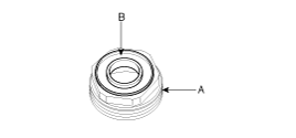
Remove the oil seal (B) from the plug (A).
|
| 7. |
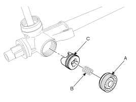
Remove the yoke plug (A) and spring (B) and then pull out the
support yoke (C).
|
| 8. |
Remove the O-rings (B) from the support yoke assembly (A).
|
| 9. |
Pull the pinion assembly (A) out of the pinion housing.
|
| 10. |
Pull the rack bar (A) out of the rack housing.
|
Inspection
| 1. |
Rack bar
|
| 2. |
Pinion assembly
|
| 3. |
Check the inside of rack housing for damage.
|
| 4. |
Check the bellows for being torn.
|
Reassembly
| 1. |
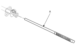
Apply the grease to rack gear teeth and then insert the rack bar
(A) into the rack hosing.
|
| 2. |
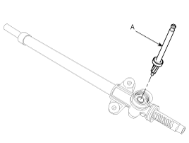
Insert the pinion assembly (A) into the pinion housing.
|
| 3. |
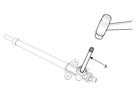
Tap the top of the pinion assembly with a plastic hammer to seat
the pinion assembly thoroughly.
|
| 4. |
Assemble new O-rings (B) to support yoke (A).
|
| 5. |
Insert the support yoke assembly (C) into the housing.
|
| 6. |
Apply the sealant to the thread of the yoke plug and then assemble
the yoke plug (A) and the yoke spring (B) together.
|
| 7. |
Apply the grease to the edge of the new oil seal (B) and then
assemble it to the pinion plug (A).
|
| 8. |
Apply the sealant to the thread of the plug and then assemble
the pinion plug (A) to the housing.
|
| 9. |
Apply loctite (Three bond-1374) to the thread of the tie rod inner
ball joint and then assemble the tie rod (A) to the rack bar (B).
|
| 10. |
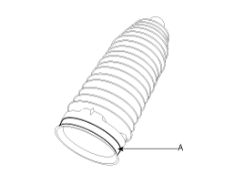
Assemble new bellows band (A) to the bellows.
|
| 11. |
Apply the grease (Kyoto Yushi-One Luber2128 to the portion (D)
of the tie-rod.
|
| 12. |
Apply the sealant (Three bond-1141E) to the bellows mating surface
of therack housing.
|
| 13. |
Assemble the bellows (C) to rack housing and then tighten the
bellows clip (A) and band (B).
|
| 14. |
Assemble the lock nut (A) and tie rod end (B) to tie rod.
|
Installation
| 1. |
Install the steering gear box (A) to the sub frame by tightening
the mounting bolts.
|
| 2. |
Install the rear roll stopper (A) to the sub frame by tightening
the mounting bolts.
|
| 3. |
Install the sub frame (E) and sub frame stay by tightening the
mounting bolts (A, C) and nuts (B, D).
|
| 4. |
Tighten the front and rear roll stopper bolt and nut (A, B).
|
| 5. |
Install the wiring harness protector to the sub-frame by tightening
the bolts (A).
|
| 6. |
Install the muffler rubber hanger (A).
|
| 7. |
Connect the lower arm with the knuckle by tightening the bolts
(A).
|
| 8. |
Connect the tie rod end with the knuckle and then install the
castle nut and split pin.
|
| 9. |
Connect the stabilizer link (A) with the front strut assembly
and than tighten the nut.
|
| 10. |
Connect the universal joint assembly (B) with the pinion of the
steering gear box and then tighten the bolt (A).
|
| 11. |
Install the front wheel & tire.
|
| 12. |
Check the alignment. (Refer to SSgroup 'Tires/Wheels - alingment')
|
| 13. |
Perform the ASP (Absoulte Steering Position) calibration procedure.
(Refer to ASP calibration)
|

