 Hyundai Elantra: Shift Lever. Repair procedures (A4CF2)
Removal
| 1. |
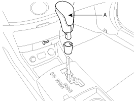
Remove the shift lever knob (A).
|
| 2. |
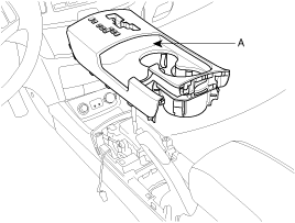
Remove the center console cover (A).
|
| 3. |
Remove the center console. (refer to Console in BD group)
|
| 4. |
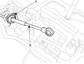
Remove the control cable assembly (B) by removing the clamp (A).
|
| 5. |
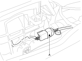
Disconnect the interlock switch connector (A).
|
| 6. |
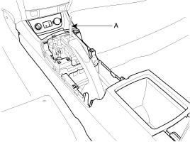
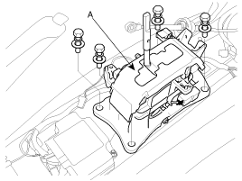
Remove the shift lever assembly (A).
|
| 7. |
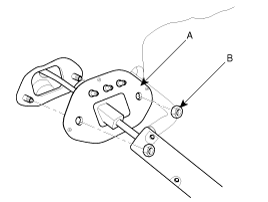
Remove the retainer (A) and nuts (B).
|
| 8. |
Remove the control cable assembly from the transaxle (refer to
Automatic transaxle's removal).
|
| 9. |
Remove the control cable assembly.
|
Installation
| 1. |
Install the control cable assembly to transaxle. (refer to Automatic
transaxle's installation)
|
| 2. |
Install the retainer (A) and nuts (B).
|
| 3. |
Install the shift lever assembly (A).
|
| 4. |
Connect the interlock switch connector (A).
|
| 5. |
Install the control cable assembly (B) by installing the clamp
(A).
|
| 6. |
Install the center console. (refer to Console in BD group)
|
| 7. |
Install the center console cover (A).
|
| 8. |
Install the shift lever knob (A).
|
Adjustment
Adjusting method for the control cable
| 1. |
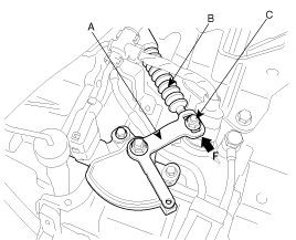
Set room side lever and T/M side lever (A) to "N" position.
|
| 2. |
Connect the room side lever and shift cable. (refer to Shift lever's
'Installation')
|
| 3. |
Connect the T/M side lever (A) to cable (B) in this following
order;
|
| 4. |
After adjusting the cable (B) according to procedure no. 2-3,
check to be sure that this part operates surely at each range of T/M
side corresponding to each position of room lever.
|

