 Hyundai Elantra: Rear Disc Brake. Repair procedures
Removal
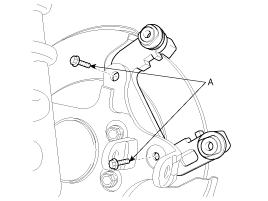
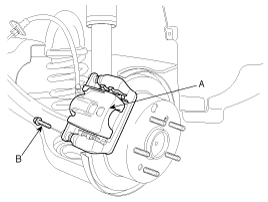
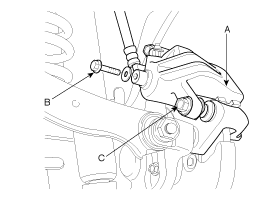
| 1. |
Remove the brake hose bolt (B) and the guide rod bolts (C) from
the caliper assembly (A).
|
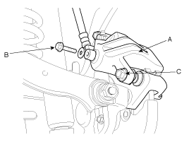
| 2. |
Remove the caliper assembly (A).
|
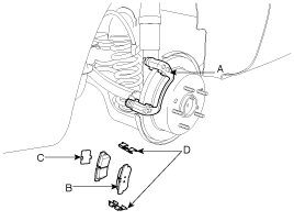
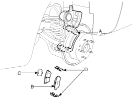
| 3. |
Remove the pads (B), the pad shims (C) and the pad springs (D)
from the caliper carrier (A).
|
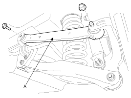
| 4. |
Remove the rear upper arm (A).
|
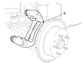
| 5. |
Remove the caliper carrier (B) and the caliper mounting bolts
(A).
|
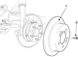
| 6. |
Remove the brake disc (A) and the screw (B).
|
Replacement
Frequent inhalation of brake pad dust, regardless of material
composition, could be hazardous to your health.
|
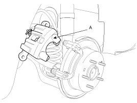
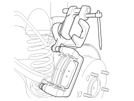
| 1. |
Remove guide rod bolt (B) and raise the caliper assembly (A).
|
| 2. |
Remove the pads (B), the pad shims (C) and the pad springs (D)
from the caliper carrier (A).
|
Inspection
Rear Brake Disc Thickness Check
| 1. |
Remove all rust and contamination from the disc surface, and then
measure the disc thickness at 8 positions at least.
|
| 2. |
Thickness variation should not exceed 0.01 mm (0.0004in) (circumference)
and 0.01 mm(0.0004 in) (radius) at any directions.
|
| 3. |
If wear exceeds the limit, replace the discs and pad assemblies
for left and right of the vehicle.
|
Rear Brake Pad Check
| 1. |
Check the pad wear. Measure the pad thickness. replace it if it
is less than the specified value.
|
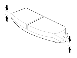
| 2. |
Check that grease is applied, to sliding contact points and the
pad and backing metal for damage.
|
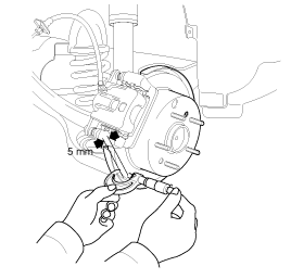
Rear Brake Disc Run Out Check
| 1. |
Place a dial gauge about 5mm (0.2 in) from the outer circumference
of the brake disc, and measure the run out of the disc.
|
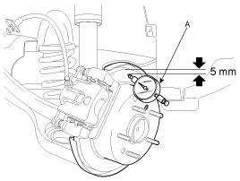
| 2. |
If the run out of the brake disc exceeds the limit specification,
replace the disc, and then measure the run out again.
|
| 3. |
If the run out does not exceed the limit specification, install
the brake disc after turning it and then check the run out of the brake
disc again.
|
| 4. |
If the run out cannot be corrected by changing the position of
the brake disc, replace the brake disc.
|
Installation
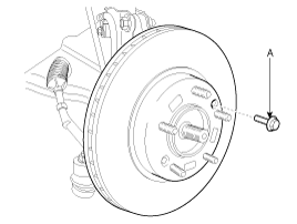
| 1. |
Install the brake disc (A) and tighten the screw (B).
|
| 2. |
Install the caliper carrier (B) and tighten the caliper mounting
bolts (A).
|
| 3. |
Install the rear upper arm (A).
|
| 4. |
Install the pad springs (D) to the caliper carrier (A).
|
| 5. |
Install the brake pads (B) and pad shims (C) on the pad retainer
correctly. Install the pad with the wear indicator on the inside. If
you are reusing the pads, always reinstall the brake pads in their original
positions to prevent a momentary loss of braking efficiency.
|
| 6. |
Push in the piston using the SST(09581-11000) so that the caliper
will fit over the pads. Make sure that the piston boot is in position
to prevent damaging it when installing the caliper.
|
| 7. |
Install the caliper assembly (A).
|
| 8. |
Install the brake hose bolt (B) and the guide rod bolts (C) to
the caliper assembly (A).
|
| 9. |
Refill the master cylinder reservoir to the MAX line.
|
| 10. |
Bleed the (Refer to "Bleeding of brake system")
|
| 11. |
Depress the brake pedal several times to make sure the brakes
work, then test-drive.
|
| 12. |
After installation, check for leaks at hose and line joints or
connections, and retighten if necessary.
|


