Hyundai Elantra: Manual Transaxle. Repair procedures (M5CF2)
Removal
|
|
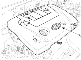
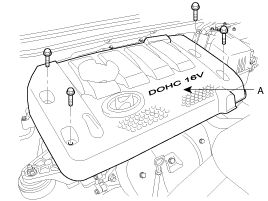
| 1. |
Remove the engine cover (A).
|
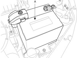
| 2. |
Remove the battery (A) after removing the battery terminal.
|
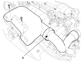
| 3. |
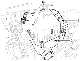
Remove the air duct assembly(A).
|
| 4. |
Remove the air cleaner assembly (C) by disconnecting the clamp
(A) and the ECM connector (B).
|
| 5. |
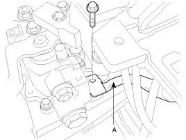
Remove the ground cable from transaxle (A).
|
| 6. |
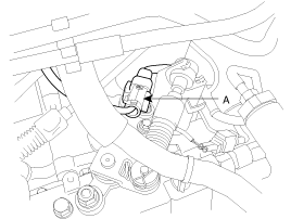
Disconnect the vehicle speed sensor and the back lamp switch integrated
connector (A).
|
| 7. |
Remove the control cable assembly (C) by removing the snap pins
(A) and clips (B).
|
| 8. |
Remove the control cable bracket (A).
|
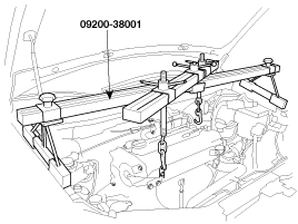
| 9. |
Using the special tool (09200-38001), support the engine assembly
safely.
|
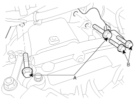
| 10. |
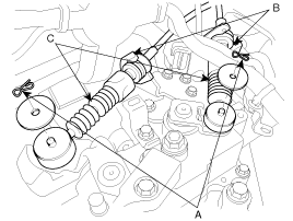
Remove the transaxle upper mounting bolts (A-2ea) and the starter
motor mounting bolts (B-2ea).
|
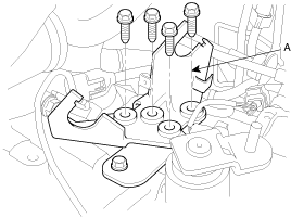
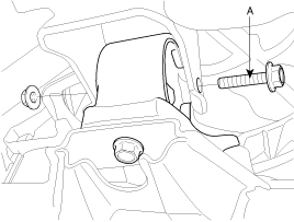
| 11. |
After removing the four bolts, take the transaxle insulator mounting
bracket (A) off.
|
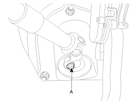
| 12. |
Remove the steering joint assembly bolt. (refer to Steering column/shaft
in ST group)
|
| 13. |
Lifting up the vehicle.
|
| 14. |
Remove the front wheels and tires.
|
| 15. |
Remove the lower arm ball joint mounting nut, the stabilizer link
mounting nut, and the tie rod end mounting nut from the front knuckles.
(refer to Front suspension system in SS group)
|
| 16. |
Remove the under shield cover(A,B).
|
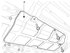
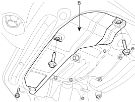
| 17. |
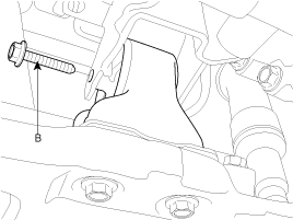
Remove the roll stopper mounting bolts (A,B).
|
| 18. |
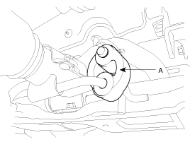
Disconnect the muffler hanger rubber (A).
|
| 19. |
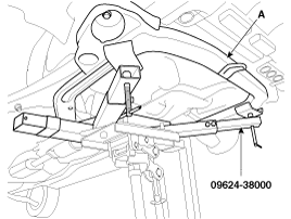
Supporting the sub frame (A) with a jack and the Special tool
(09624-38000), remove the mounting bolts.(refer to Stabilizer removal
in SS group)
|
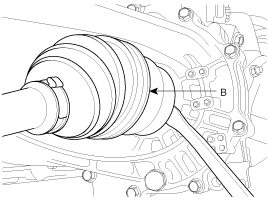
| 20. |
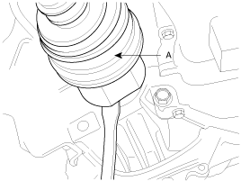
Disconnect the drive shafts (A,B) from the transaxle.
|
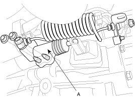
| 21. |
Remove the clutch release cylinder assembly (A).
|
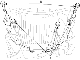
| 22. |
Supporting the transaxle with a jack, remove the transaxle lower
mounting bolts(A-3ea, B-2ea).
|
| 23. |
Lowering the jack slowly, remove the transaxle.
|
Installation
| 1. |
Install the transaxle lower mounting bolts (A-3ea,B-2ea) after
fitting the transaxle assembly into the engine assembly.
|
| 2. |
Install the clutch release cylinder assembly (A).
|
| 3. |
Connect the drive shafts (A,B) to the transaxle.
|
| 4. |
Supporting the sub frame (A) with a jack and the Special tool(09624-38000),
install the mounting bolts. (refer to Stabilizer installation in SS
group)
|
| 5. |
Install the muffler hanger rubber (A).
|
| 6. |
Install the roll stopper bracket bolts. (A,B)
|
| 7. |
Install the under shield cover(A,B).
|
| 8. |
Install the lower arm ball joint mounting nut, the stabilizer
link mounting nut, and the tie rod end mounting nut to the front knuckles.
(refer to Front suspension system in SS group)
|
| 9. |
Install the front wheels and tires. (refer to installation in
SS group)
|
| 10. |
Install the steering joint assembly bolt (A). (refer to Steering
column/shaft in ST group)
|
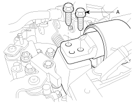
| 11. |
Install the transaxle insulator mounting bracket bolts (A).
|
| 12. |
Remove the special tool (09200-38001).
|
| 13. |
Install the transaxle upper mounting bolts (A-2ea) the starter
motor mounting bolts. (B-2ea).
|
| 14. |
Install the control cable bracket (A).
|
| 15. |
Connect the vehicle speed sensor and the back lamp switch integrated
connector (A).
|
| 16. |
Install the control cable assembly (A) by installing the clips
(B) and pins (C).
|
| 17. |
Install the ground cable (A) to transaxle.
|
| 18. |
Install the air cleaner assembly (C) by connecting the clamp (A)
and the ECM connector (B).
|
| 19. |
Install the air duct assembly (A).
|
| 20. |
Install the battery (A) and the battery terminal.
|
| 21. |
Install the engine cover (A).
|