 Hyundai Elantra: ECM Terminal And Input/Output signal (M/T)
| ECM Terminal Function |
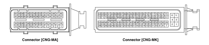
Connector [CNG-MA]
|
Pin No. |
Description |
Connected to |
|
1 |
Ignition Coil (Cylinder #1) control output |
Ignition Coil (Cylinder #1) [Without Immobilizer] |
|
Ignition Coil (Cylinder #4) control output |
Ignition Coil (Cylinder #4) [With Immobilizer] |
|
|
2 |
Injector (Cylinder #1) control output |
Injector (Cylinder #1) |
|
3 |
- |
|
|
4 |
- |
|
|
5 |
Heated Oxygen Sensor (HO2S) [Bank 1/Sensor 2] Heater control output |
Heated Oxygen Sensor (HO2S) [Bank 1/Sensor 2] |
|
6 |
Sensor ground |
Heated Oxygen Sensor (HO2S) [Bank 1/Sensor 2] |
|
7 |
Heated Oxygen Sensor (HO2S) [Bank 1/Sensor 2] signal input |
Heated Oxygen Sensor (HO2S) [Bank 1/Sensor 2] |
|
8 |
Knock Sensor (KS) signal input |
Knock Sensor (KS) |
|
9 |
Intake Air Temperature Sensor (IATS) signal input |
Intake Air Temperature Sensor (IATS) |
|
10 |
Start Motor contol switch |
Power Distribution Module (PDM) |
|
11 |
Electrical load signal input |
Alternator |
|
12 |
Engine Coolant Temperature Sensor (ECTS) signal input |
Engine Coolant Temperature Sensor (ECTS) |
|
13 |
Throttle Position Sensor (TPS) 1 signal input |
Throttle Position Sensor (TPS) 1 |
|
14 |
Sensor power (+5V) |
Throttle Position Sensor (TPS) 1,2 |
|
15 |
ETC Motor [+] control output |
ETC Motor |
|
16 |
Ignition Coil (Cylinder #3) control output |
Ignition Coil (Cylinder #3) [Without Immobilizer] |
|
Ignition Coil (Cylinder #2) control output |
Ignition Coil (Cylinder #2) [With Immobilizer] |
|
|
17 |
Injector (Cylinder #3) control output |
Injector (Cylinder #3) |
|
18 |
Purge Control Solenoid Valve (PCSV) control output |
Purge Control Solenoid Valve (PCSV) |
|
19 |
Variable Intake Solenoid (VIS) Valve control output |
Variable Intake Solenoid (VIS) Valve |
|
20 |
- |
|
|
21 |
- |
|
|
22 |
Sensor shield ground |
Knock Sensor (KS) |
|
23 |
Sensor ground |
Knock Sensor (KS) |
|
24 |
Sensor ground |
Manifold Absolute Pressure Sensor (MAPS) |
|
25 |
Sensor ground |
Battery Sensor |
|
26 |
- |
|
|
27 |
Sensor ground |
Engine Coolant Temperature Sensor (ECTS) |
|
28 |
Throttle Position Sensor (TPS) 2 signal input |
Throttle Position Sensor (TPS) 2 |
|
29 |
Sensor ground |
Throttle Position Sensor (TPS) 1,2 |
|
30 |
ETC Motor [-] control output |
ETC Motor |
|
31 |
Ignition Coil (Cylinder #4) control output |
Ignition Coil (Cylinder #4) [Without Immobilizer] |
|
Ignition Coil (Cylinder #1) control output |
Ignition Coil (Cylinder #1) [With Immobilizer] |
|
|
32 |
Injector (Cylinder #4) control output |
Injector (Cylinder #4) |
|
33 |
CVVT Oil Control (OCV) Valve [Bank 1/Intake] control output |
CVVT Oil Control Valve (OCV) [Bank 1/Intake] |
|
34 |
CVVT Oil Control (OCV) Valve [Bank 1/Exhaust] control output |
CVVT Oil Control Valve (OCV) [Bank 1/Exhaust] |
|
35 |
Sensor power (+5V) |
Variable Charge Motion Actuator (VCMA) |
|
Battery Sensor |
||
|
36 |
VG (Virtual Ground) |
Heated Oxygen Sensor [Bank 1/Sensor 1] |
|
37 |
VIP (Current Pump) |
Heated Oxygen Sensor [Bank 1/Sensor 1] |
|
38 |
VRC (Current Adjust) |
Heated Oxygen Sensor [Bank 1/Sensor 1] |
|
39 |
Manifold Absolute Pressure Sensor (MAPS) signal input |
Manifold Absolute Pressure Sensor (MAPS) |
|
40 |
Battery Sensor signal |
Battery Sensor |
|
41 |
Sensor ground |
Crankshaft Position Sensor (CKPS) |
|
42 |
Sensor ground |
Camshaft Position Sensor (CMPS) [Bank 1/Exhaust] |
|
43 |
Sensor ground |
Camshaft Position Sensor (CMPS) [Bank 1/Intake] |
|
44 |
Sensor ground |
Variable Charge Motion Actuator (VCMA) |
|
45 |
Motor [+] control output |
Variable Charge Motion Actuator (VCMA) |
|
46 |
Ignition Coil (Cylinder #2) control output |
Ignition Coil (Cylinder #2) [Without Immobilizer] |
|
Ignition Coil (Cylinder #3) control output |
Ignition Coil (Cylinder #3) [With Immobilizer] |
|
|
47 |
Injector (Cylinder #2) control output |
Injector (Cylinder #2) |
|
48 |
- |
|
|
49 |
Alternator PWM control output |
Alternator |
|
50 |
Heated Oxygen Sensor (HO2S) [Bank 1/Sensor 1] Heater control output |
Heated Oxygen Sensor (HO2S) [Bank 1/Sensor 1] |
|
51 |
- |
|
|
52 |
VN (NERNST Cell Voltage) |
Heated Oxygen Sensor [Bank 1/Sensor 1] |
|
53 |
- |
|
|
54 |
Sensor power (+5V) |
Manifold Absolute Pressure Sensor (MAPS) |
|
55 |
Battery Current Direct input |
Battery Sensor |
|
56 |
Crankshaft Position Sensor (CKPS) signal input |
Crankshaft Position Sensor (CKPS) |
|
57 |
Camshaft Position Sensor (CMPS) [Bank 1/Exhaust] signal input |
Camshaft Position Sensor (CMPS) [Bank 1/Exhaust] |
|
58 |
Camshaft Position Sensor (CMPS) [Bank 1/Intake] signal input |
Camshaft Position Sensor (CMPS) [Bank 1/Intake] |
|
59 |
Sensor feedback signal input |
Variable Charge Motion Actuator (VCMA) |
|
60 |
Motor [-] control output |
Variable Charge Motion Actuator (VCMA) |
Connector [CNG-MK]
|
Pin No. |
Description |
Connected to |
|
1 |
Power ground |
Chassis Ground |
|
2 |
Battery power (B+) |
Main Relay |
|
3 |
Power ground |
Chassis Ground |
|
4 |
Battery power (B+) |
Main Relay |
|
5 |
Power ground |
Chassis Ground |
|
6 |
Battery power (B+) |
Main Relay |
|
7 |
- |
|
|
8 |
- |
|
|
9 |
- |
|
|
10 |
- |
|
|
11 |
A/C Compressor Relay control output |
A/C Compressor Relay |
|
12 |
Engine speed signal output |
Power Distribution Module (PDM) |
|
13 |
- |
|
|
14 |
- |
|
|
15 |
Fuel Tank Pressure Sensor (FTPS) signal input |
Fuel Tank Pressure Sensor (FTPS) |
|
16 |
- |
|
|
17 |
- |
|
|
18 |
- |
|
|
19 |
- |
|
|
20 |
Electrical load [Wiper] signal input |
Wiper [Low] Relay |
|
21 |
- |
|
|
22 |
- |
|
|
23 |
- |
|
|
24 |
- |
|
|
25 |
Fuel Level Sensor (FLS) signal input |
Fuel Level Sensor (FLS) |
|
26 |
- |
|
|
27 |
- |
|
|
28 |
- |
|
|
29 |
- |
|
|
30 |
- |
|
|
31 |
- |
|
|
32 |
- |
|
|
33 |
- |
|
|
34 |
Immobilizer Lamp control output |
Immobilizer Lamp |
|
35 |
- |
|
|
36 |
Canister Close Valve (CCV) control output |
Canister Close Valve (CCV) |
|
37 |
Sensor ground |
Fuel Tank Pressure Sensor (FTPS) |
|
38 |
- |
|
|
39 |
- |
|
|
40 |
- |
|
|
41 |
- |
|
|
42 |
- |
|
|
43 |
- |
|
|
44 |
- |
|
|
45 |
Sensor ground |
A/C Pressure Transducer (APT) |
|
46 |
- |
|
|
47 |
Sensor ground |
Fuel Level Sensor (FLS) |
|
48 |
- |
|
|
49 |
Sensor ground |
Accelerator Position Sensor (APS) 1 |
|
50 |
Sensor ground |
Accelerator Position Sensor (APS) 2 |
|
51 |
Battery power (B+) |
Ignition Switch |
|
52 |
Start Motor relay control output |
Start Motor relay |
|
53 |
Cooling Fan Relay [High] control output |
Cooling Fan Relay [High] |
|
54 |
Cooling Fan Relay [Low] control output |
Cooling Fan Relay [Low] |
|
55 |
CCP CAN [High] |
Other control module, Data Link Connector (DLC), |
|
56 |
CCP CAN [Low] |
Other control module, Data Link Connector (DLC), |
|
57 |
- |
|
|
58 |
- |
|
|
59 |
- |
|
|
60 |
- |
|
|
61 |
- |
|
|
62 |
Brake Test Switch signal input |
Brake Switch |
|
63 |
- |
|
|
64 |
Blower Max. signal input |
Heater & A/C Control module |
|
65 |
- |
|
|
66 |
- |
|
|
67 |
A/C Pressure Transducer (APT) signal input |
A/C Pressure Transducer (APT) |
|
68 |
A/C Compressor switch signal output |
A/C Compressor switch |
|
69 |
Immobilizer communication line |
Immobilizer control module |
|
70 |
- |
|
|
71 |
Accelerator Position Sensor (APS) 1 signal input |
Accelerator Position Sensor (APS) 1 |
|
72 |
Accelerator Position Sensor (APS) 2 signal input |
Accelerator Position Sensor (APS) 2 |
|
73 |
Battery power (B+) |
Battery |
|
74 |
Main Relay control output |
Main Relay |
|
75 |
Fuel Pump Relay control output |
Fuel Pump Relay |
|
76 |
- |
|
|
77 |
C-CAN [High] |
Other control module, Data Link Connector (DLC), |
|
78 |
C-CAN [Low] |
Other control module, Data Link Connector (DLC), |
|
79 |
Clutch switch signal input |
Clutch switch |
|
80 |
Vehicle speed signal input |


