Description
Anti-theft Warning System
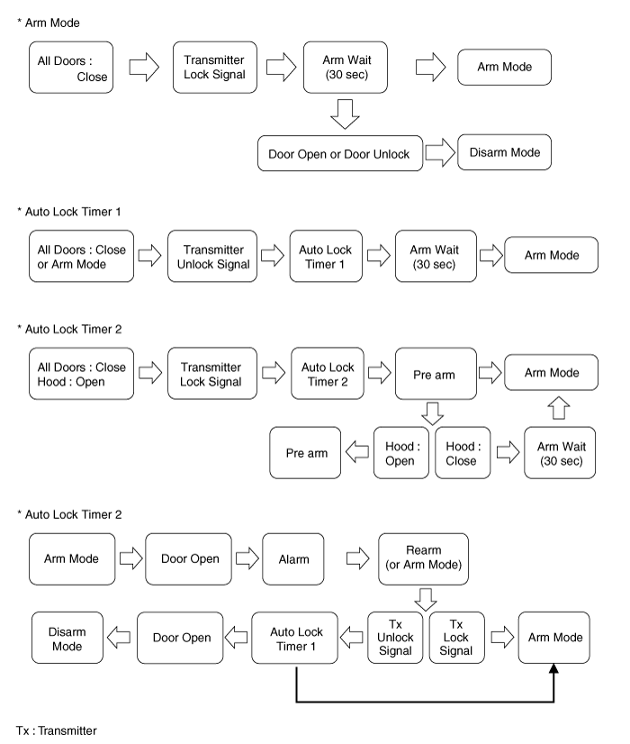
Burglar Alarm System
The burglar alarm system is armed automatically after the
doors, hood, and trunk are closed and locked.
The system is set off when any of these things occur :
| • |
A door is forced open.
|
| • |
The trunk is opened without using the key.
|
When the system is set off, the alarm sounds and the hazard
lamp flash for about 30 seconds or until the system is disarmed by unlocking
the transmitter.
For the system to arm, the ignition switch must be off and
the key removed. Then, the body control module must receive signals that the
doors, hood, and trunk are closed and locked. When everything is closed and
locked, none of the control unit inputs are grounded.
The door switches, hood switch and trunk switch are all close
and lock the doors with the remote transmitter and then the system arms immediately.
If anything is opened after the system is armed, the body
control module gets a ground signal from that switch, and the system is set
off.
If one of the switches is misadjusted or there is a short
in the system, the system will not arm. As long as the body control module continues
to get a ground signal, it thinks the vehicle is not closed and locked and will
not arm.
Keyless Entry System
The burglar alarm system is integrated with the keyless entry
system. The keyless entry system allows you to lock and unlock the vehicle with
the remote transmitter. When you push the LOCK/UNLOCK button, all doors lock.
When you push the LOCK/UNLOCK button again, all doors unlock.
The room lamp, if its switch is in the center position, will
come on when you press the UNLOCK button. If you do not open a door, the light
will go off in about 30 seconds, the doors will automatically relock, and the
burglar alarm system will rearm. If you relock the doors with the remote transmitter
within 30 seconds, the light will go off immediately.
You cannot lock or unlock the doors with the remote transmitter
if the key is in the ignition switch.
The system will signal you when the doors lock and unlock
by flashing the hazard lamp once when they lock, and twice when they unlock.
Function
Keyless Entry Function
DOOR LOCK / UNLOCK, TRUNK and panic operation are performed
with remocon
|
1. |
Keyless entry function is performed in a state that
key in SW is eliminated from key cylinder
|
|
2. |
LOCK / UNLOCK, TRUNK and panic signals are received
from the transmitter and DOOR LOCK / UNLOCK, TRUNK and panic signals
are output.
|
Transmitter(TX) Spec
|
1. |
Transmission Distance : 30m or more from outside
of the car
|
|
2. |
Registration procedure of the transmitter
|
(1) |
In registration mode, it shall be possible
to register up to Max 4EA.
|
|
(2) |
At re-registration, data are registered newly
after deleting the previous TX DATA
No.
|
Saved CODE
|
CODE to change
|
Changed CODE
|
1
|
-
|
A
|
A
|
2
|
A
|
B
|
B (A is deleted)
|
3
|
B
|
C, D
|
C, D (B is deleted)
|
4
|
C, D
|
E, F, G
|
E, F, G (C, D is deleted)
|
5
|
E, F, G
|
H, I, J, K
|
H, I, J, K (E, F, G are deleted)
|
6
|
A, B
|
C, F, E, F, G
|
C, F, E, F
|
7
|
A, B
|
C, C, D, E, F
|
C, F, E,
|
8
|
A, B, C, D
|
A
|
A
|
9
|
A, B, C, D
|
E
|
E
|
|
|
(3) |
For the registration procedures by using
Hi-scan tool, refer to "TRANSMITTER CODE REGISTRATION".
|
|
|
3. |
Transmitter signal & Receiver Spec
|
(1) |
Transmission signal
| A. |
Transmit relevant transmission DATA
(Transmission frame) twice by pushing TX SW.
|
| B. |
Only LOCK signal is output when pushing
TX LOCK SW and UNLOCK SW at the same time.
|
|
|
DISARM
Condition 1
State
|
Description
|
Initial Condition
|
ALARM state
|
Event
|
| •
|
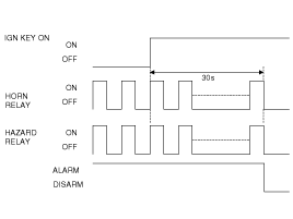
IGN KEY ON during 30sec or ALT"L" = ON
|
| •
|
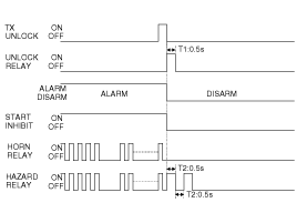
TX(Transmitter) Unlock & Any Door open(4Door
SW ON)
|
| •
|
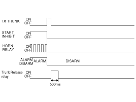
TX(Transmitter) Trunk
|
| •
|
TX(Transmitter) Lock & Lock confirm failed
|
| •
|
Driver door key unlock switch ON.
|
| •
|
Driver door key lock SW ON & Lock confirm
failed
|
|
Action
|
| •
|
The state goes to DISARM state
|
| •
|
Hazard relay off, Horn relay off and start
inhibit relay off.
|
|
- |
Unlock relay on for 0.5 sec.
|
|
- |
Hazard relay on (TWICE)
|
|
|
Condition 2
State
|
Description
|
Initial Condition
|
DISARM state & (IGN KEY OUT) & Any Door open
|
Event
|
|
Action
|
|
- |
Unlock relay on for 0.5 sec
|
|
- |
Hazard relay on (Twice)
|
|
|
Condition 3
State
|
Description
|
Initial Condition
|
ARMWAIT state
|
Event
|
| •
|
At least one entrance opened
|
| •
|
Driver door key unlock SW ON
|
|
Action
|
The state goes to DISARM state
|
Condition 4
State
|
Description
|
Initial Condition
|
AUTOLOCKTIMER1 state
|
Event
|
| •
|
At least one entrance opened
|
| •
|
Lock by AUTOLOCK, but Lock confirmation failure
|
| •
|
Tx Lock, but Lock confirmation failure
|
| •
|
Driver door key unlock SW ON, but Lock confirmation
failure
|
|
Action
|
| •
|
The state goes to DISARM state
|
|
Condition 5
State
|
Description
|
Initial Condition
|
AUTOLOCKTIMER2 state
|
Event
|
| •
|
Hood Open & Memory Hood was Close
|
| •
|
Trunk Open & Memory Trunk was Close
|
| •
|
Lock by AUTOLOCK, but Lock confirmation failure
|
| •
|
Tx Lock, but Lock confirmation failure
|
| •
|
Driver door key unlock SW ON, but Lock confirmation
failure
|
|
Action
|
| •
|
The state goes to DISARM state
|
|
Condition 6
State
|
Description
|
Initial Condition
|
ARM state or ARM HOLD state
|
Event
|
| •
|
Driver door key unlock SW ON
|
|
Action
|
| •
|
The state goes to DISARM state
|
|
Condition 7
State
|
Description
|
Initial Condition
|
REARM state
|
Event
|
| •
|
IGN KEY ON during 30sec or ALT"L" = ON
|
| •
|
Tx Lock, but Lock confirmation failure
|
| •
|
Driver door key unlock SW ON
|
| •
|
Driver door key unlock SW ON & Lock confirmation
failure
|
|
Action
|
| •
|
The state goes to DISARM state
|
| •
|
Start Inhibit relay OFF
|
|
Condition 8
State
|
Description
|
Initial Condition
|
PREARM state
|
Event
|
| •
|
All entrance closed & Any Door is unlocked
|
| •
|
Any Door open & Tx Unlock
|
|
Action
|
| •
|
The state goes to DISARM state
|
|
- |
Unlock relay on for 0.5sec
|
|
- |
Hazard relay on (Twice)
|
|
|
ARM
Condition 1
State
|
Description
|
Initial Condition
|
ARM state
|
Event
|
|
Action
|
| •
|
Hazard relay 1Time on(1sec)
|
|
Condition 2
State
|
Description
|
Initial Condition
|
ARMHOLD state
|
Event
|
| •
|
Trunk closed for at least Trunk Release Time
Out(default 30s)
|
|
Action
|
| •
|
The state goes to ARM state
|
|
Condition 3
State
|
Description
|
Initial Condition
|
ARMWAIT state
|
Event
|
| •
|
ARMWAITTIMER is expired
|
|
Action
|
| •
|
The state goes to ARM state
|
|
ALARM
Condition 1
State
|
Description
|
Initial Condition
|
ARM state
|
Event
|
| •
|
Any entrance open (DOORS, TRUNK, or HOOD)
|
|
Action
|
| •
|
The state goes to ALARM state
|
| •
|
The horn rings 3 times with 27sec(±2sec)
on 10sec(±2sec)off
|
| •
|
The hazard is driven also (During Horn driving)
|
| •
|
Engine Start Inhibit is ON
|
|
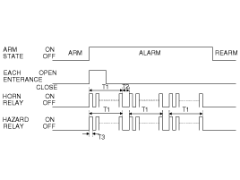
T1 : 27s (±2sec), T2 : 10s (±2sec),
T3 : 0.5s ± 0.1 sec.
|
Horn Output : Period : 1sec(Can be calibrated Horn
Period), 50% Duty
|
Condition 2
State
|
Description
|
Initial Condition
|
ARMHOLD state
|
Event
|
| •
|
Any door open or Hood open
|
|
Action
|
| •
|
The state goes to ALARM state
|
| •
|
The horn rings 3 times with 27sec(±2sec)
on 10sec(±2sec) off
|
| •
|
The hazard is driven also (During Horn driving)
|
| •
|
Engine Start Inhibit is ON
|
|
Condition 3
State
|
Description
|
Initial Condition
|
REARM state
|
Event
|
| •
|
Any door open or Hood open or Trunk open
|
|
Action
|
| •
|
The state goes to ALARM state
|
| •
|
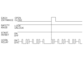
The horn rings 3 times with 27sec(±2sec)
on 10sec(±2sec) off
|
|
ARM WAIT MODE
Condition 1
State
|
Description
|
Initial Condition
|
ARMWAIT state
|
Event
|
|
Action
|
| •
|
The state goes to State
|
|
- |
Hazard relay 1 Time on(1sec)
|
|
|
Condition 2
State
|
Description
|
Initial Condition
|
DISARM state & IGN KEY OUT & All entrances closed (DOORS,
HOOD and TRUNK)
|
Event
|
| •
|
Tx Lock & locked confirmed
|
| •
|
Driver door key lock SW ON & Locked confirmed
|
| •
|
All doors locked & All doors closed (All
doors not closed 1→0)
|
|
Action
|
| •
|
The state goes to ARMWAIT State
|
| •
|
Hazard relay 1Time on(1sec)
|
|
Condition 3
State
|
Description
|
Initial Condition
|
ALARM state & All entrances closed(DOORS, HOOD and TRUNK)
|
Event
|
| •
|
Tx Lock & locked confirmed
|
| •
|
Driver door key lock SW ON & Locked confirmed
|
|
Action
|
Component Location
1. Hood switch
2. Burglar horn
3. Body control module
4. Key warning switch
5. Front door switch
6. Front door lock actuator & switch
...
Inspection
Burglar Alarm Horn Relay
Check for continuity between the terminals.
1.
There should be continuity between the No.8 and No.18
terminals when power a ...
|
 Hyundai Elantra: Description and Operation


